
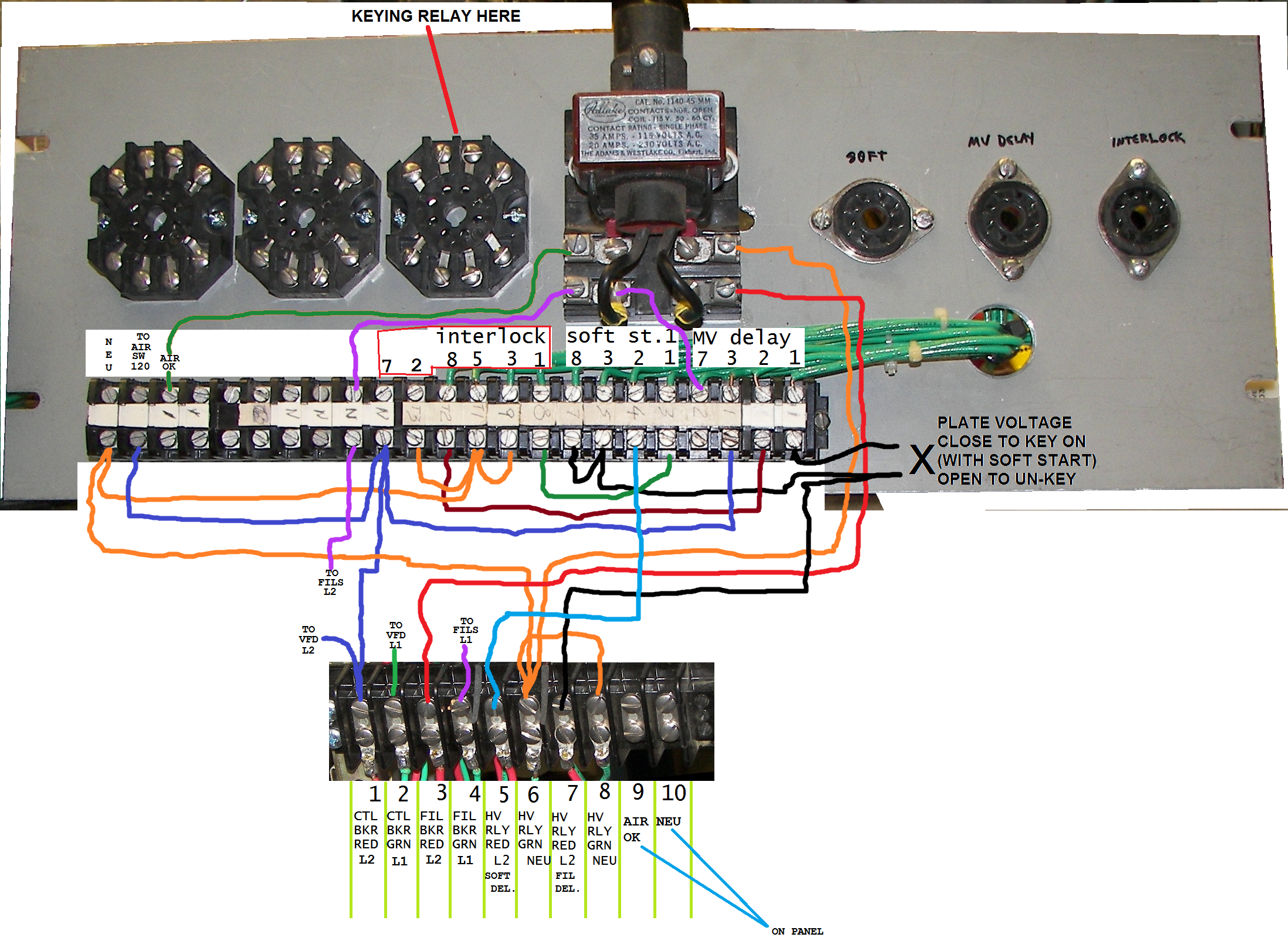
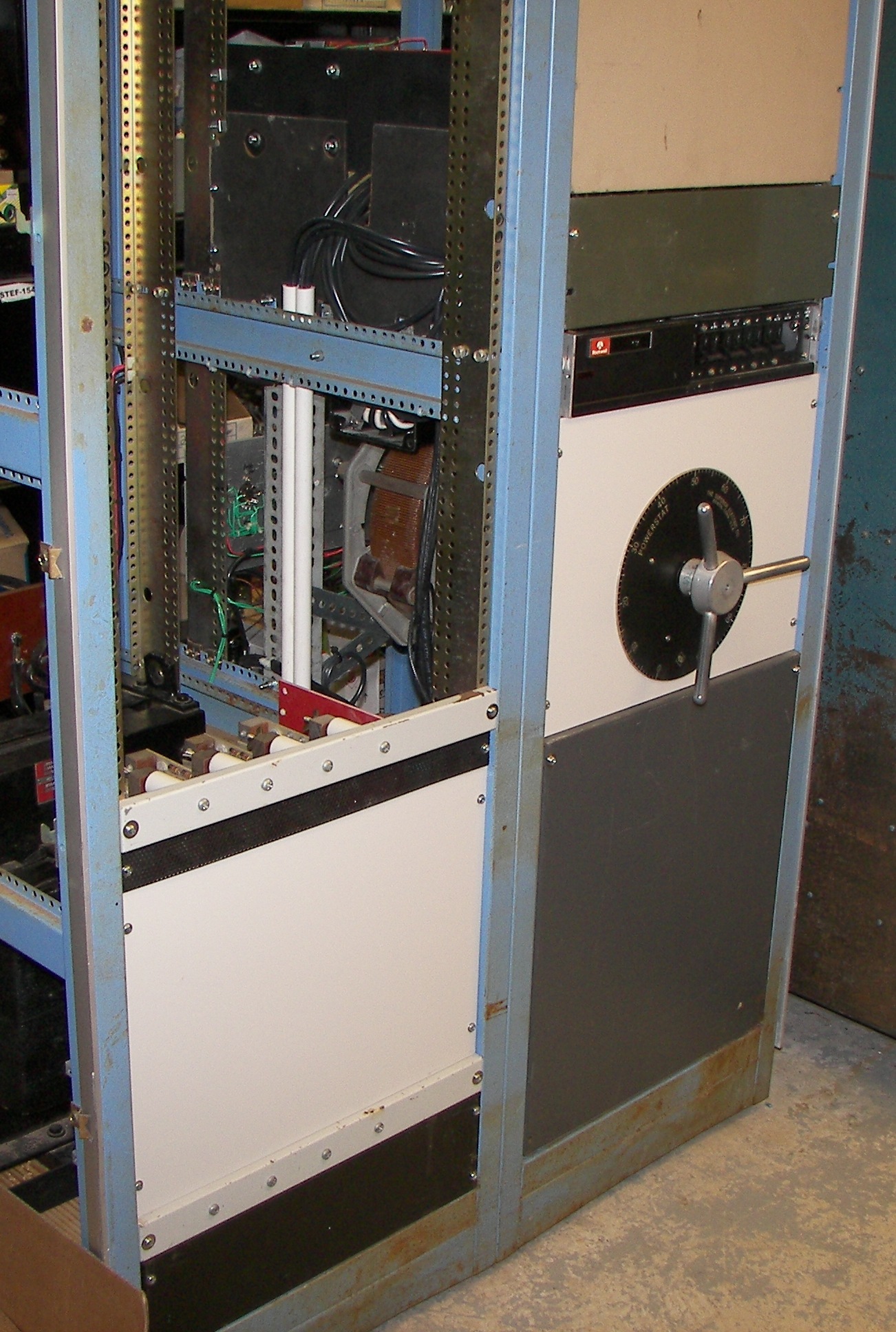
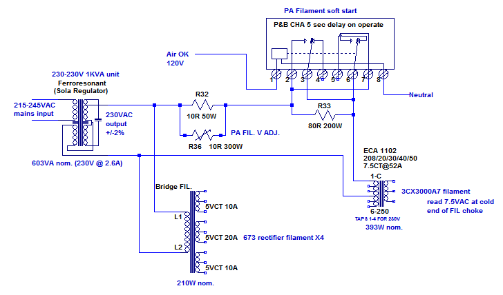
Schematic of project (work in progress contains errors, last updated May 16, 2017) |
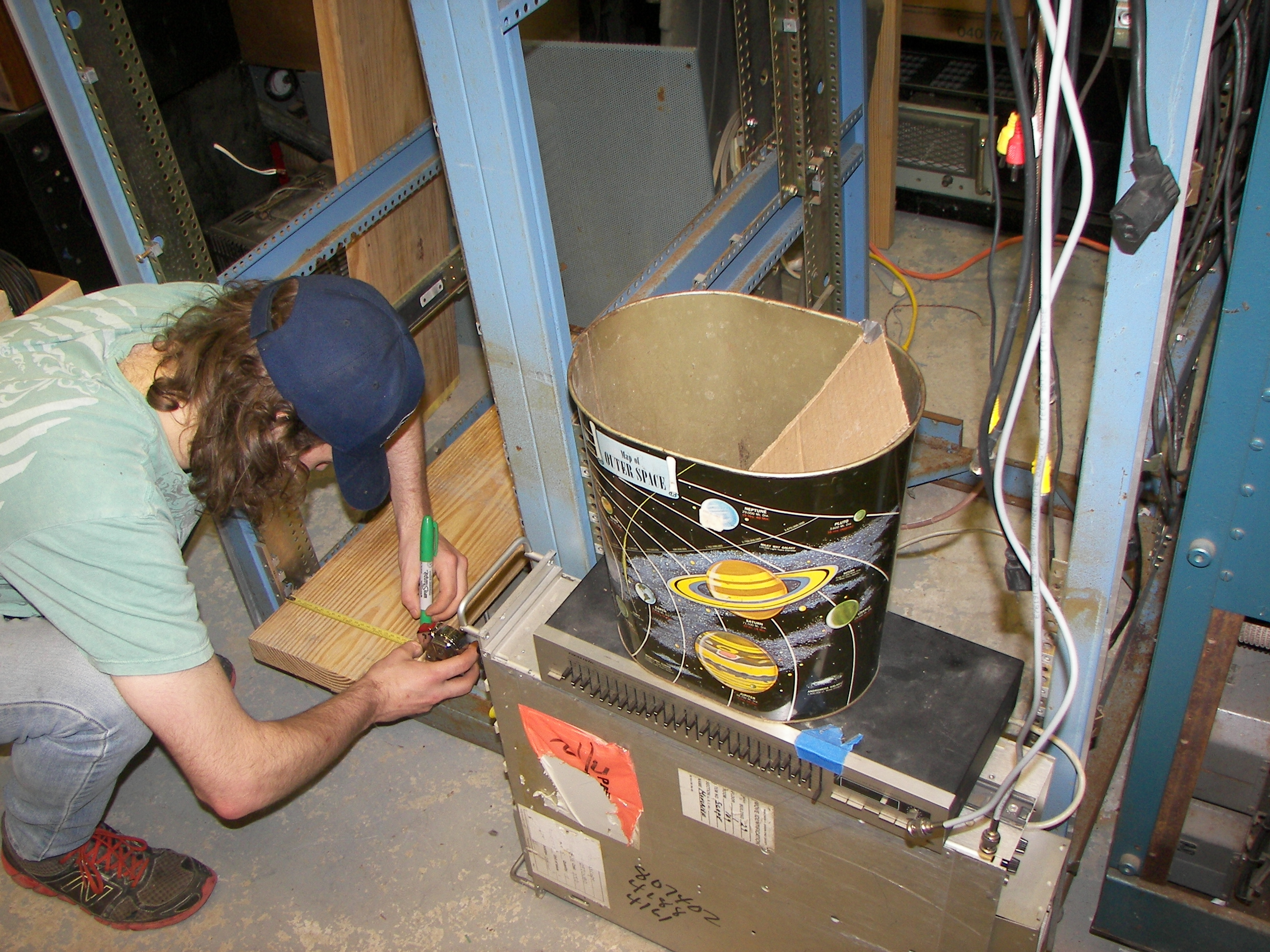
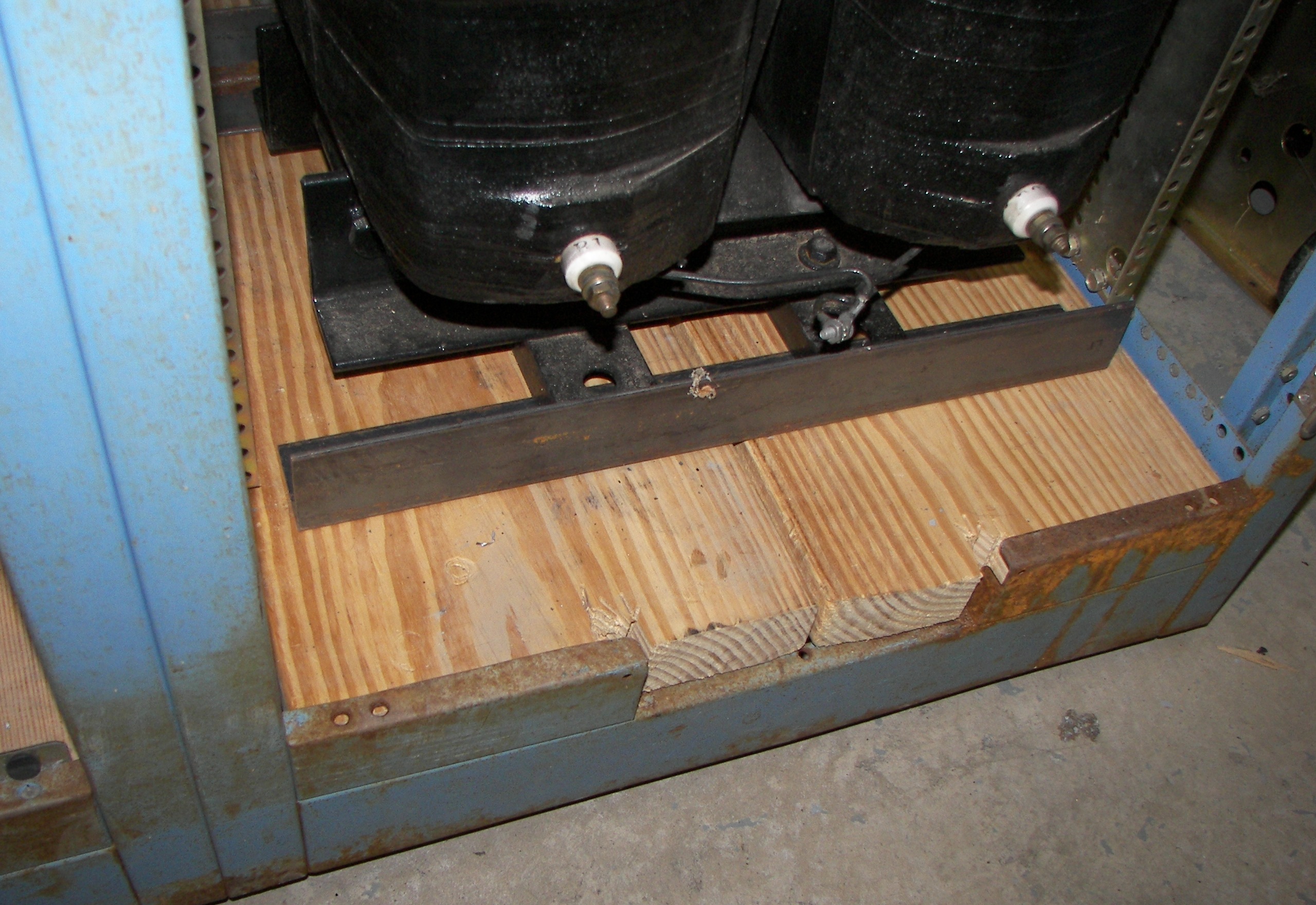
A first step: Mr. Adcock carefully measuring for the cuts on the 2x10 lumber to be the floor of the racks. |

The width turned out to be a perfect snug fit. The length was a little tricky because some flanges projected into space disallowing the planks to rst on the front and rear support areas in the bottom of the racks. |
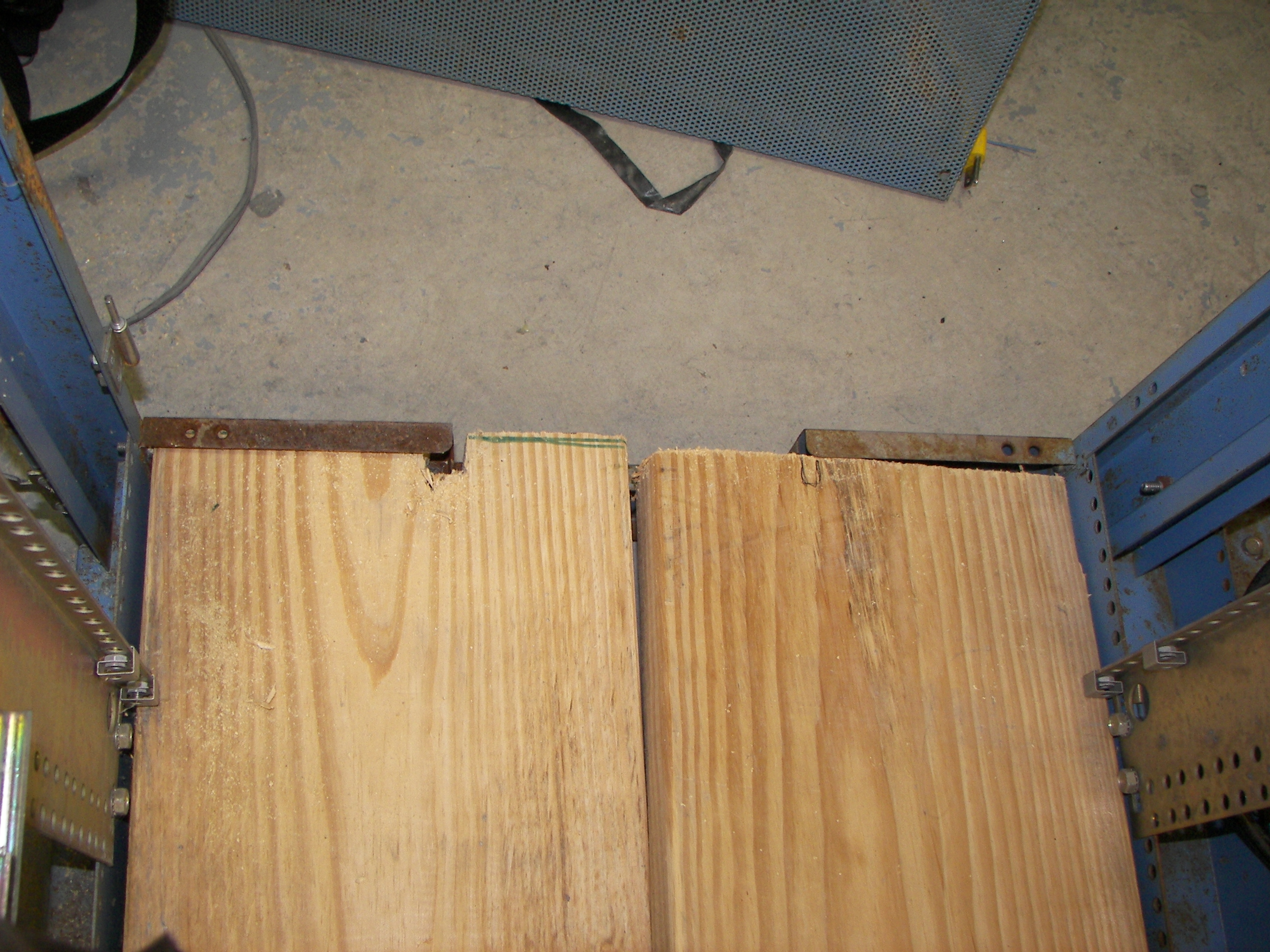
Notches cut into the planks let them just fit. |
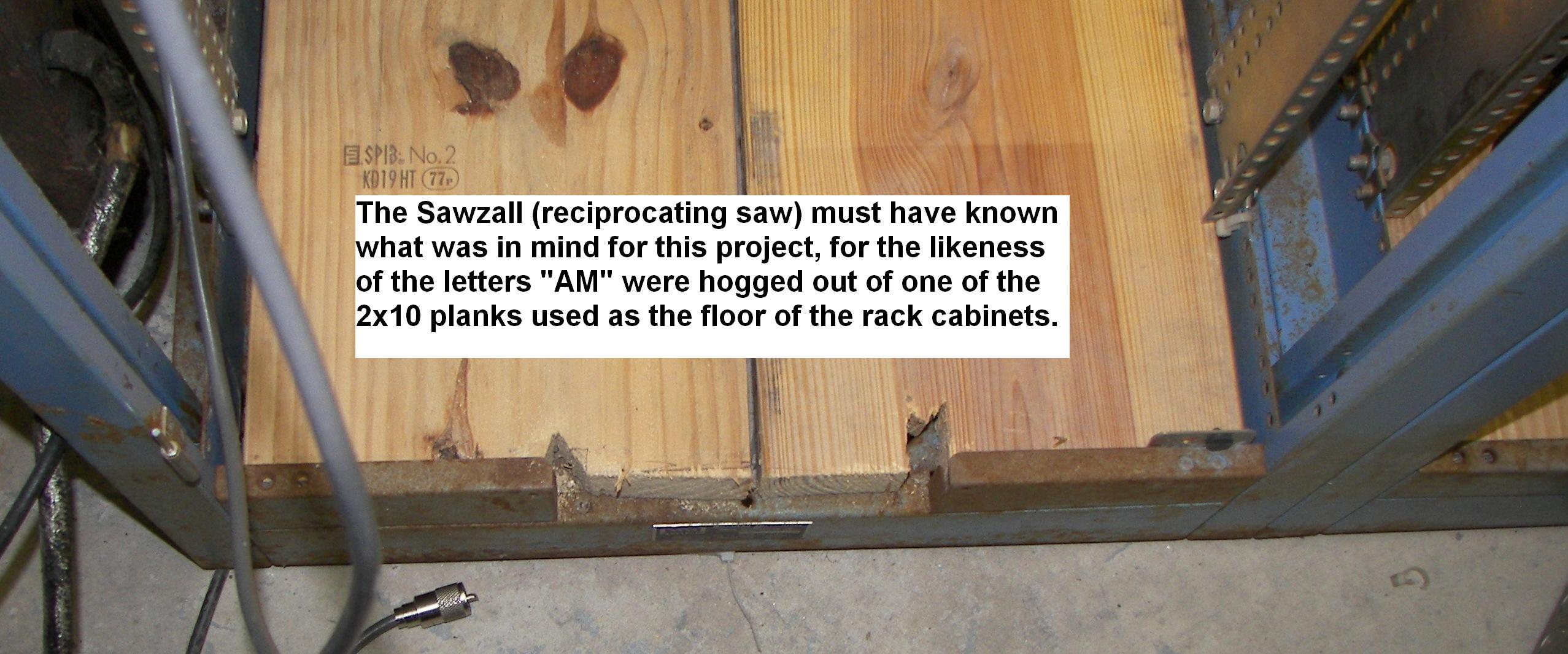
The cuts on one side randomly ended up looking like "AM". It is appropriate because this is amplifier designed for 100% duty cycle in any mode, and AM is especially difficult for any linear amplifier due to low efficiency at carrier level. |
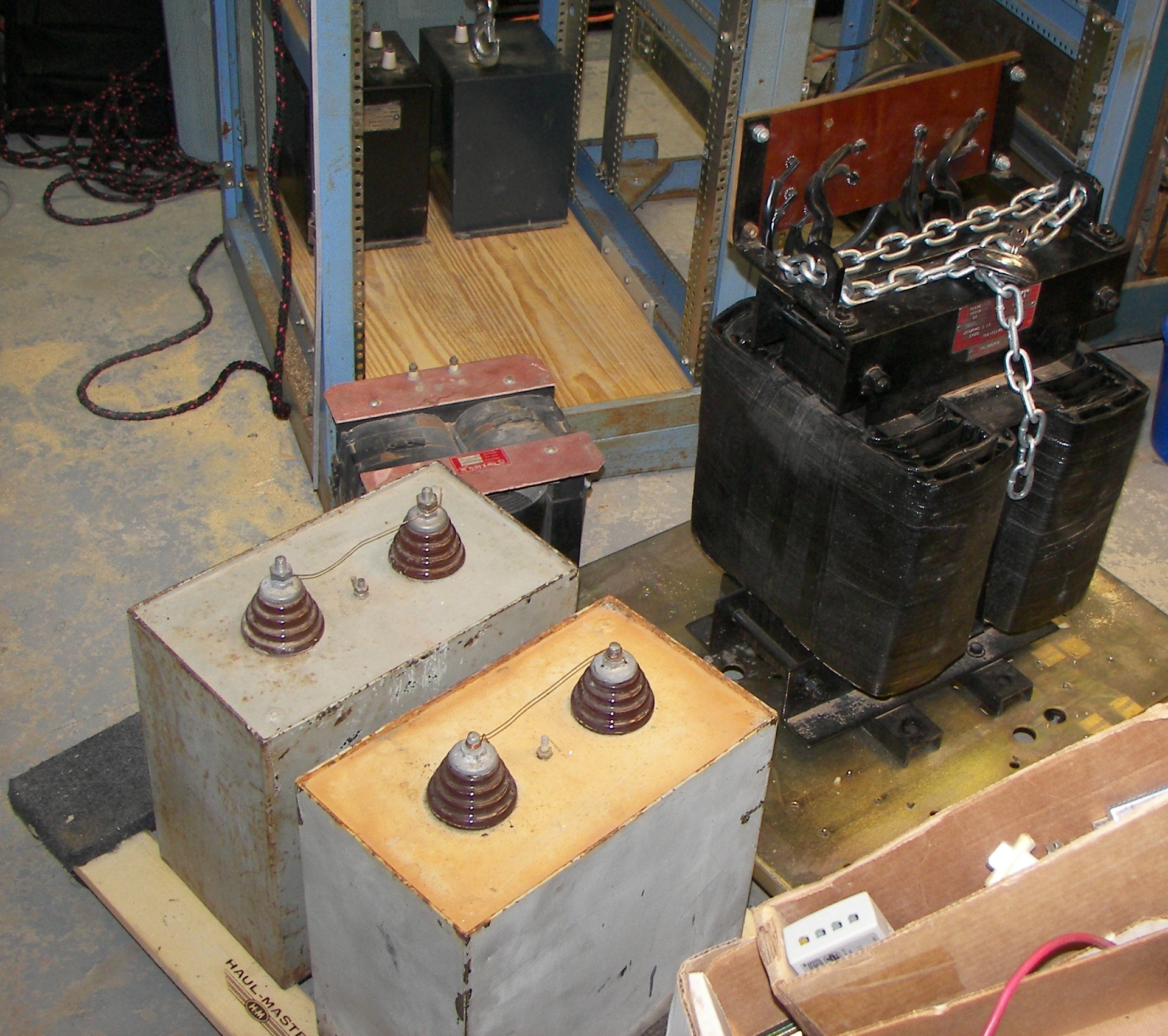
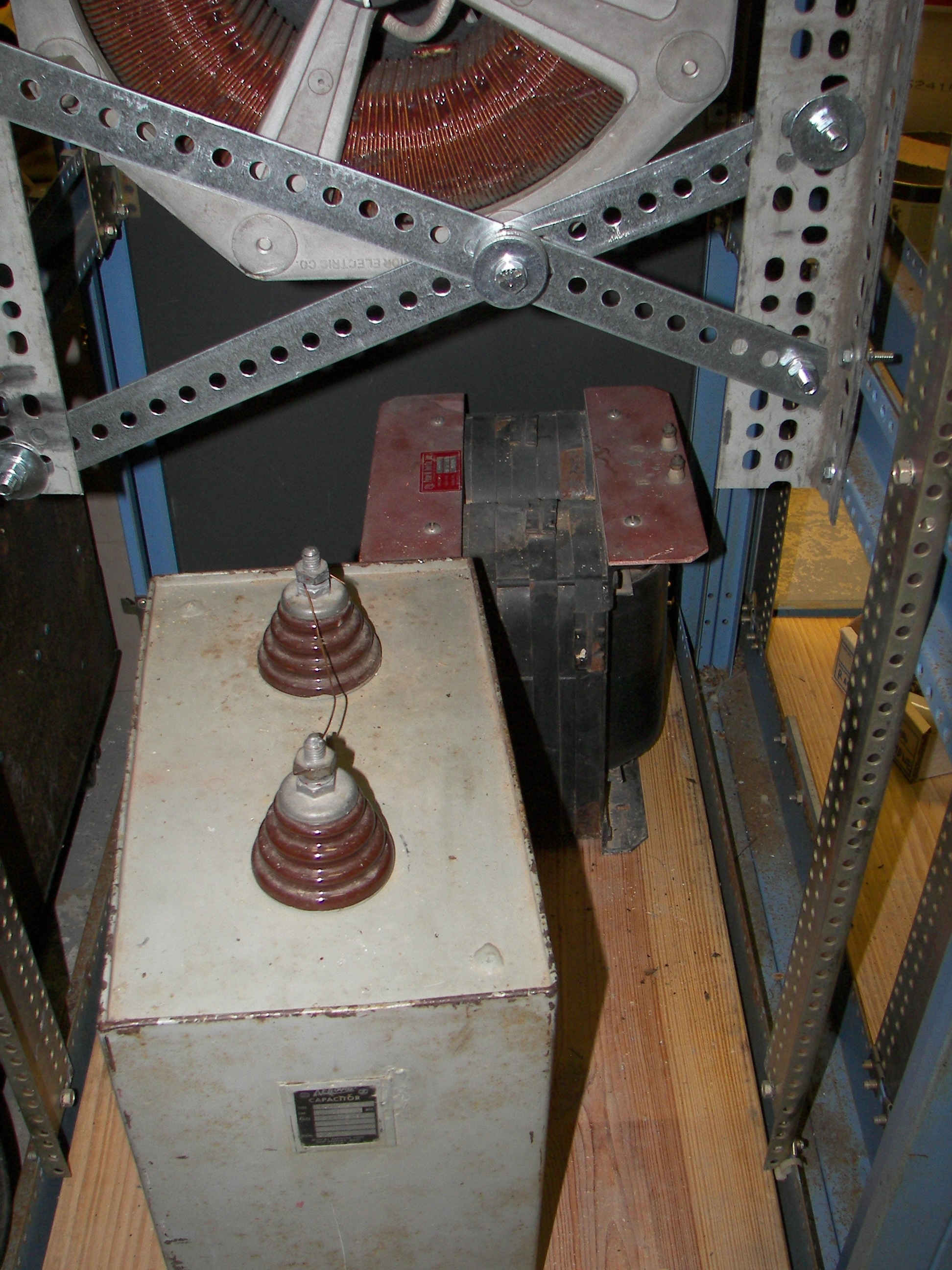
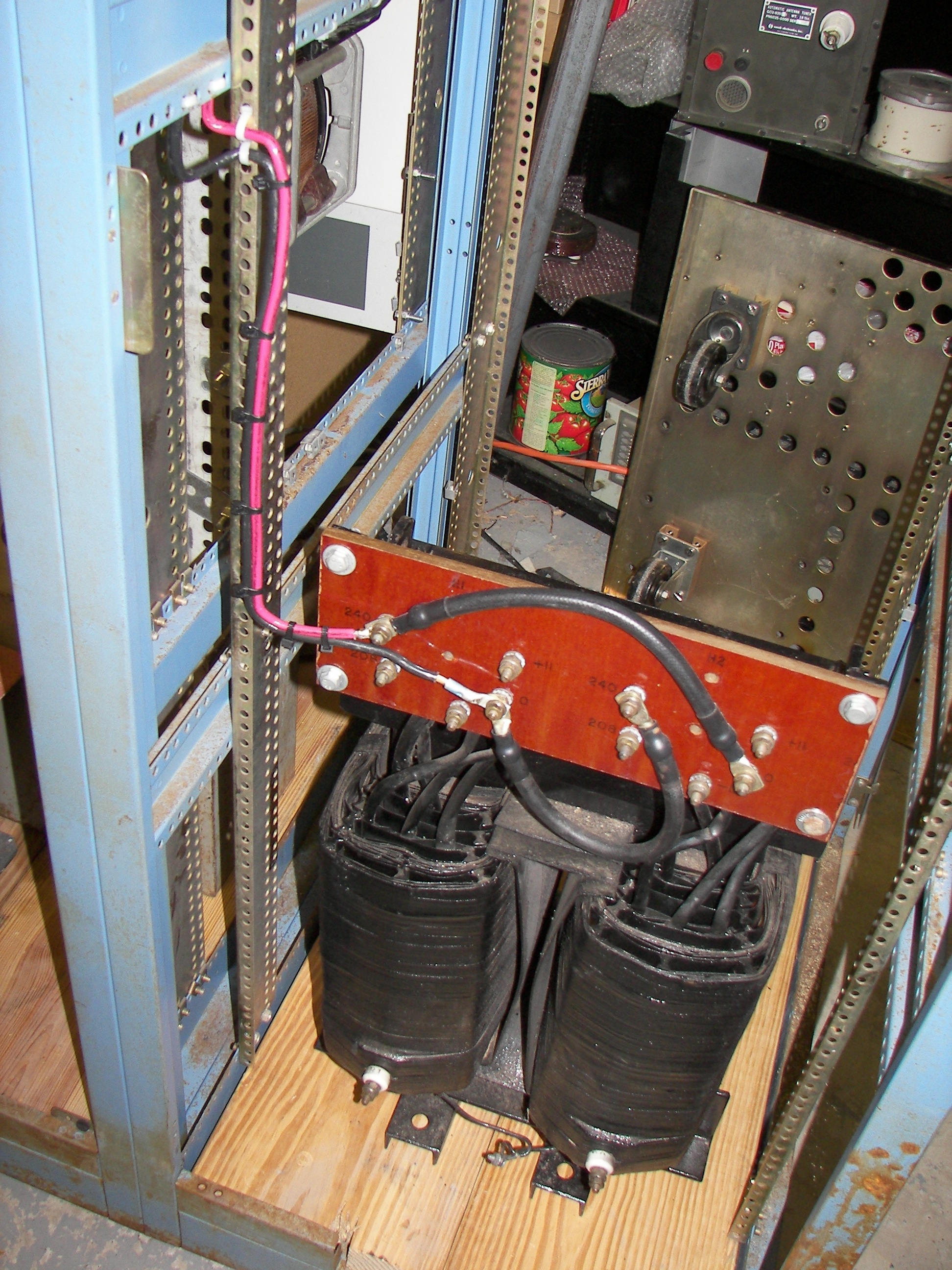
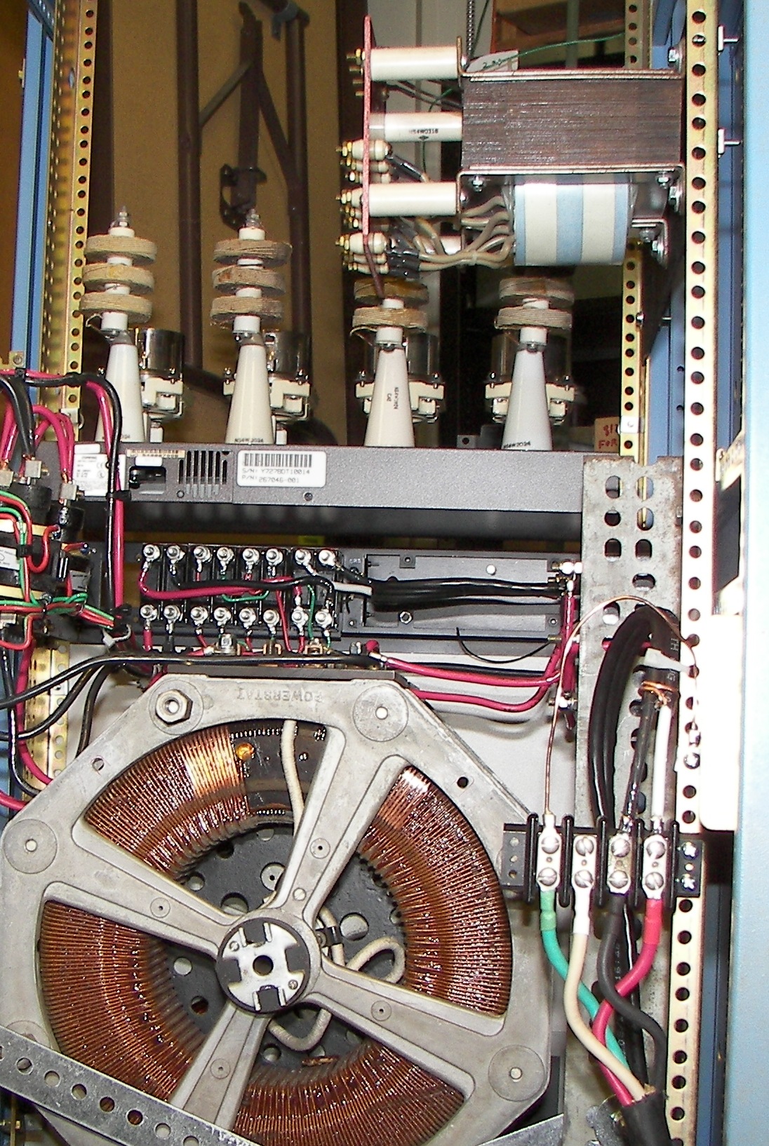
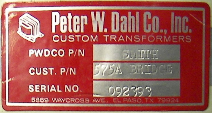
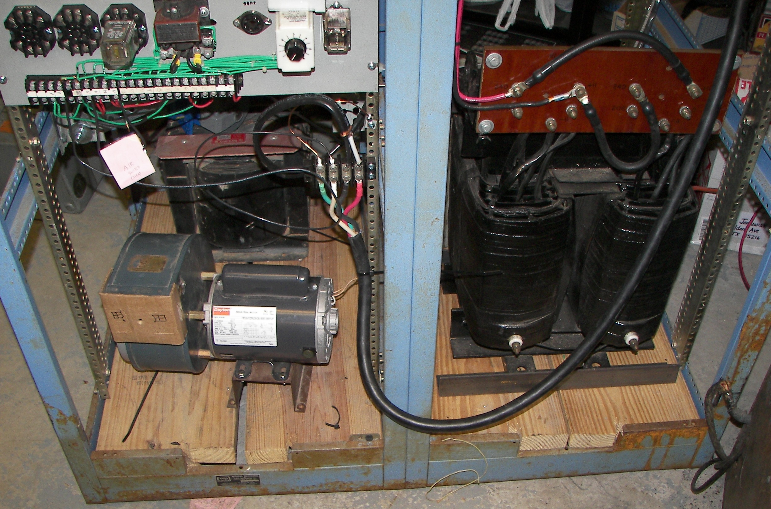
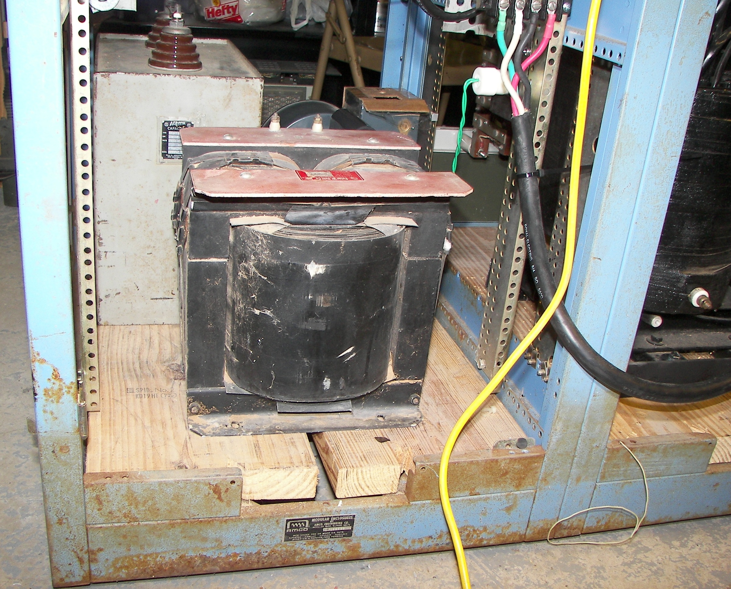
Major power supply components, all CCS rated, that is, designed to run 24x7 for decades and of course made in the United States: 5620V @ 3.5A (20KVA) plate transformer and a couple of 31.5uF 9.5KV oil-filled filter capacitors. Only one caacitor will be used, and choke will also be used to get excellent regulation and avoid high peak current in the rectifiers. The choke is 30H@1.3A and the capacitor is 31.25uF@9600V. About the choke, the tube's data sheet says 2A max but as an amplifier the would only happen on in CW condition, so 1.3A should be enough. Not sure how to calculate that right now but it is a great choke and should be fine in here. The end-installed filter may alternately be resonant if a suitable LC setup can be had and that will provide fine transient response. |

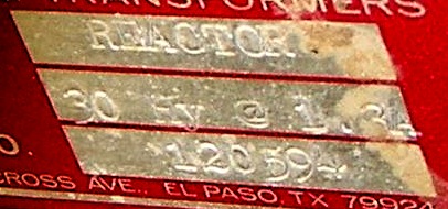
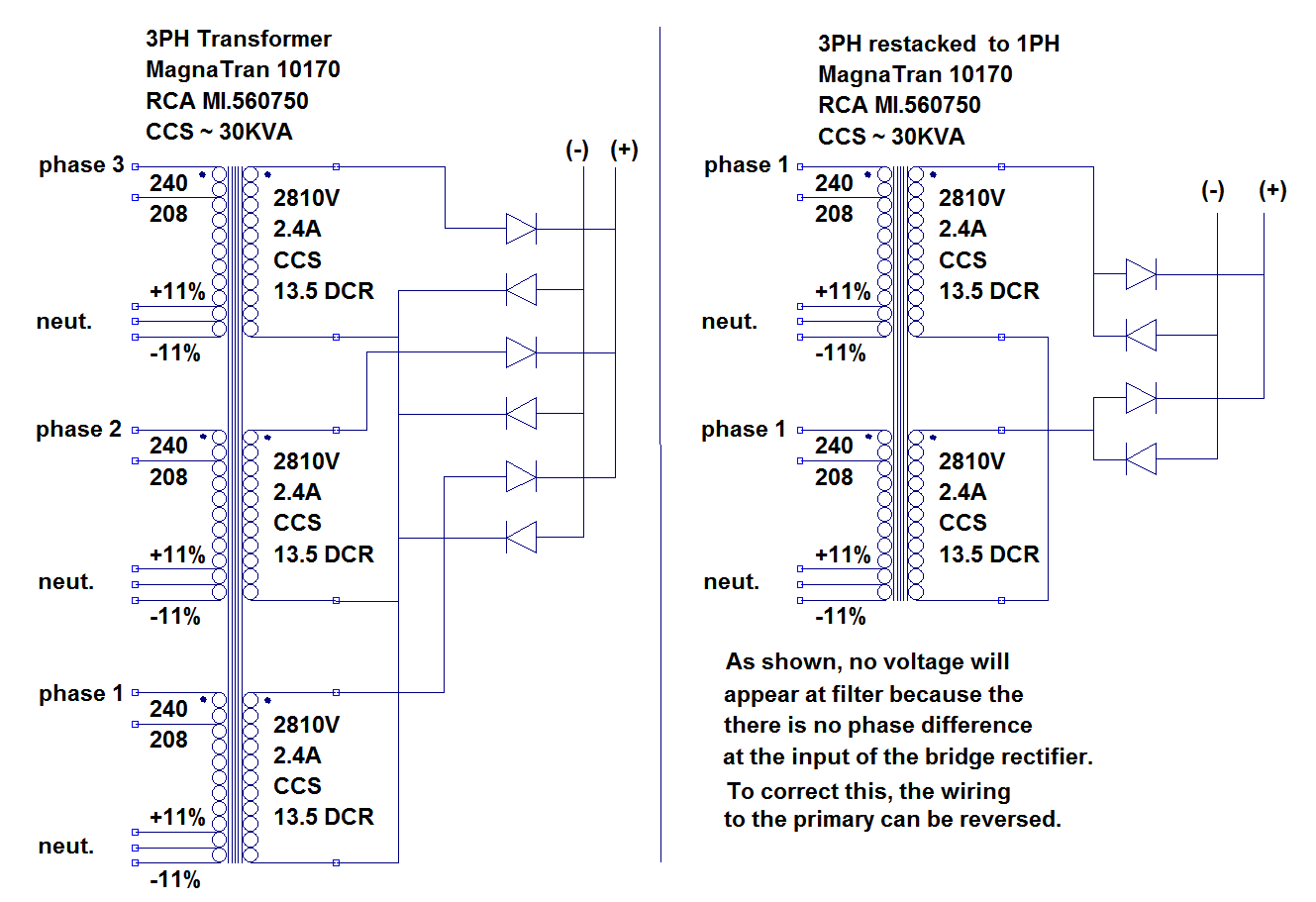
Transformer name plate shows this was remanufactured from a 3-phase transformer. |

|
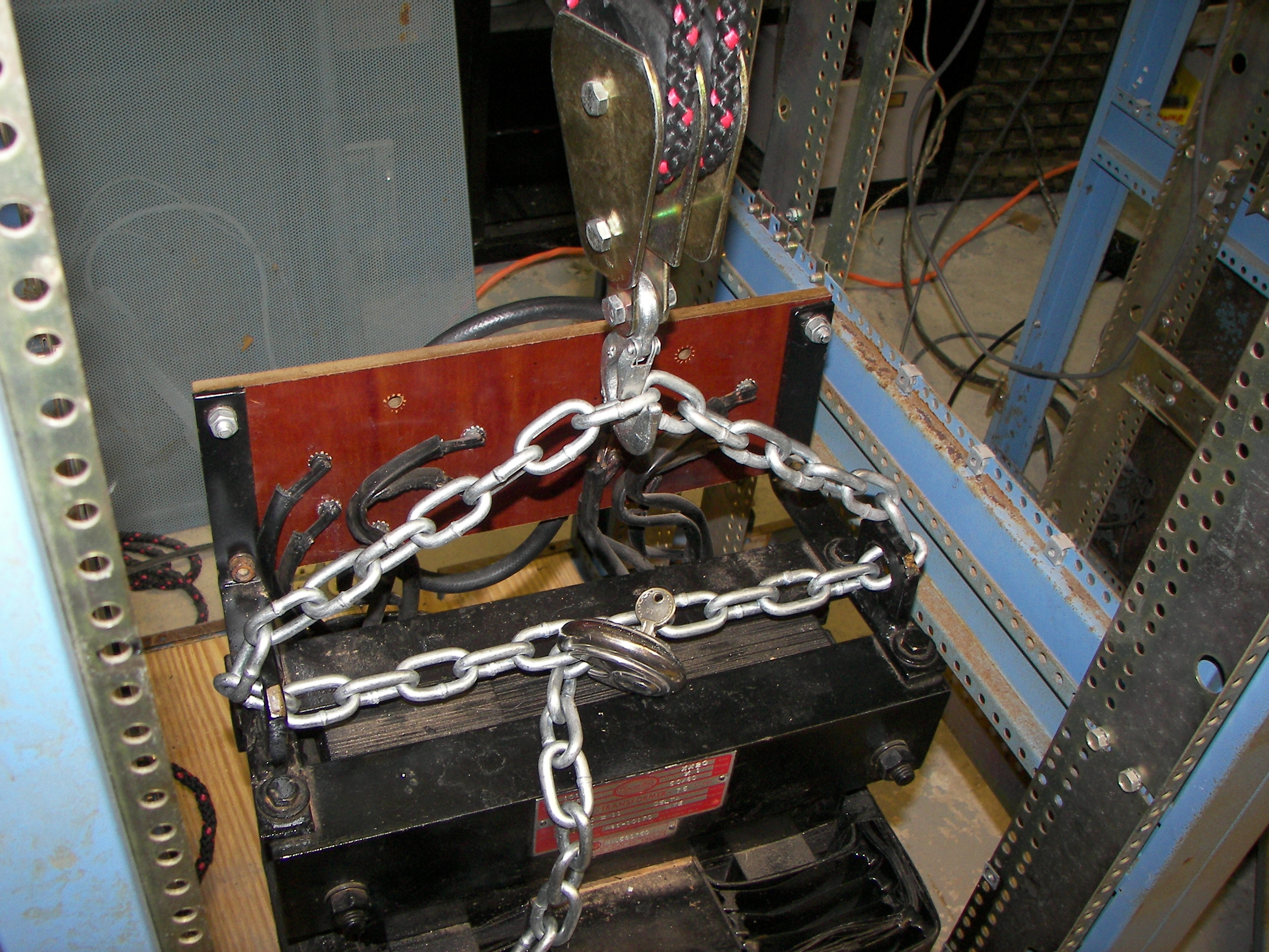
The transformer weighs about 400 Lbs. A smaller one could have been used but this was available and inexpensive. |
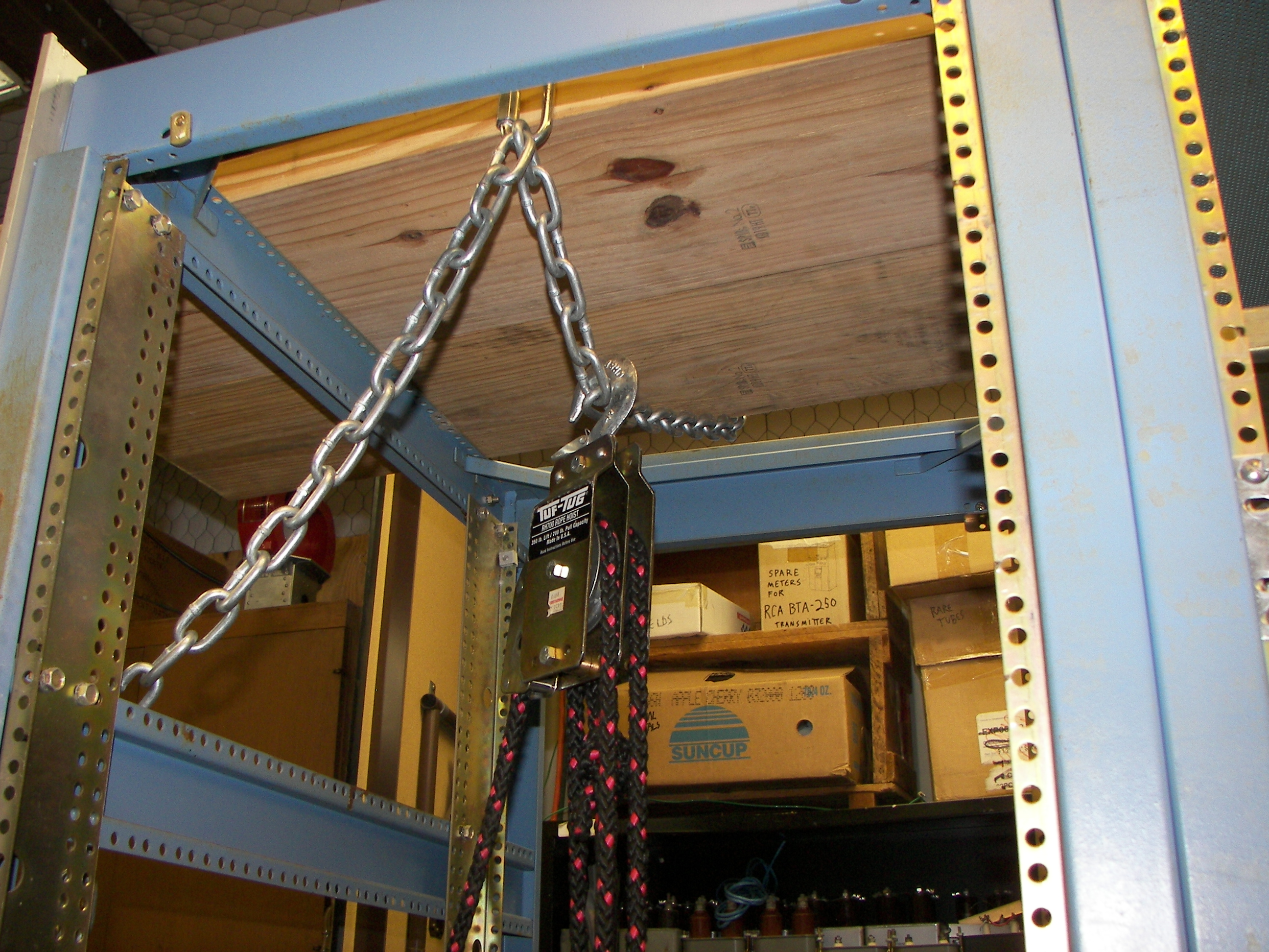
This 700 LB rated block was used to 'get holt of' the transformer and swing/drag it carefully into the rack. |
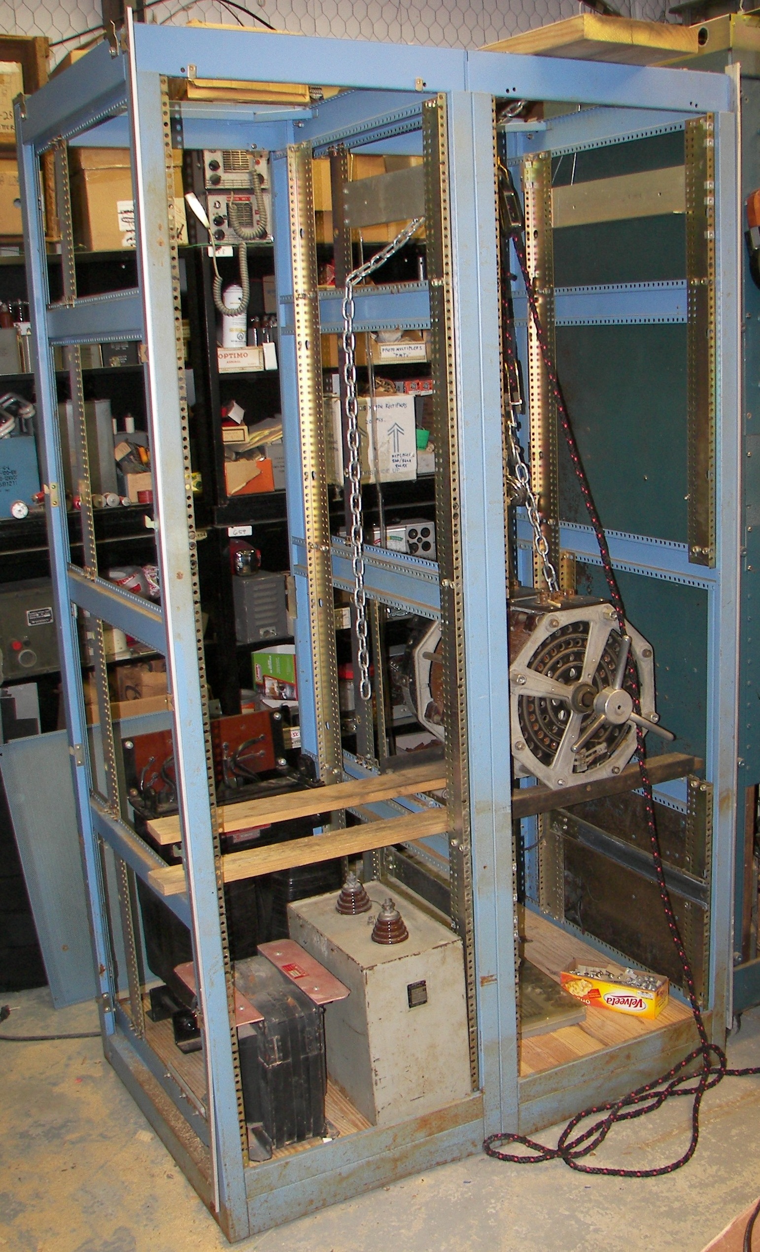
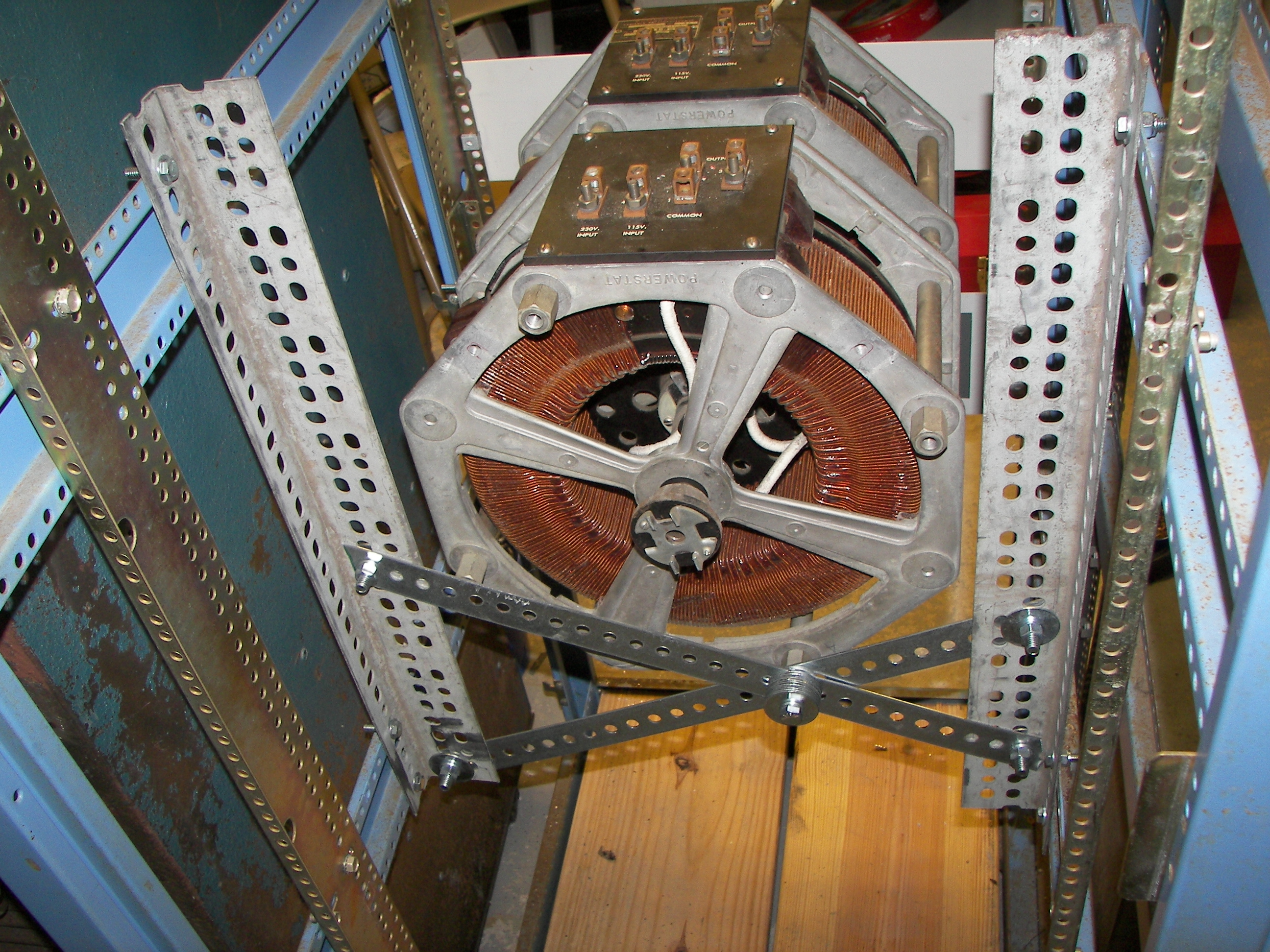
The block was note done. The next job was to hoist the Plate Powerstat into place and set it temporarily on the 2x4 boards. |
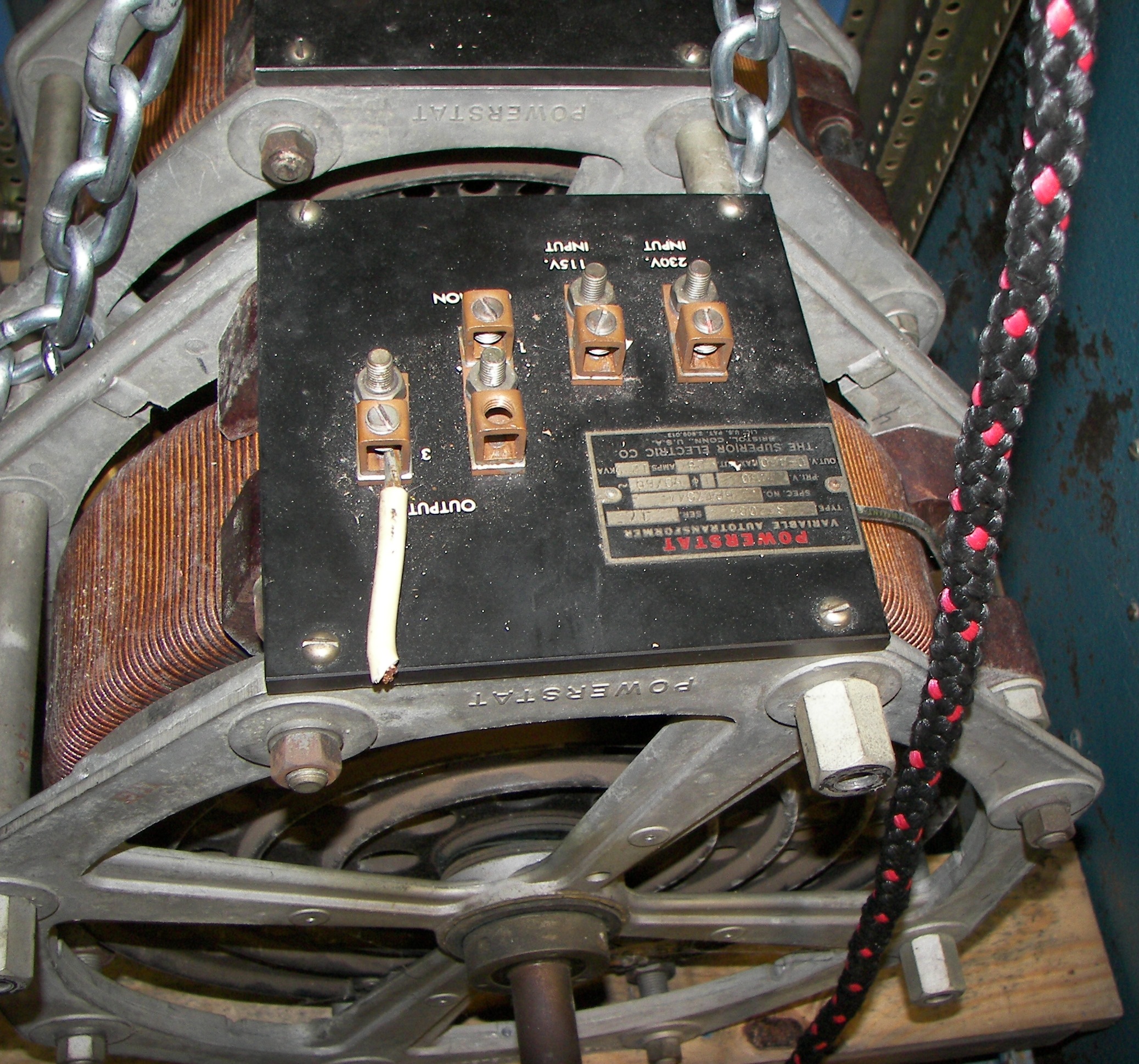
|

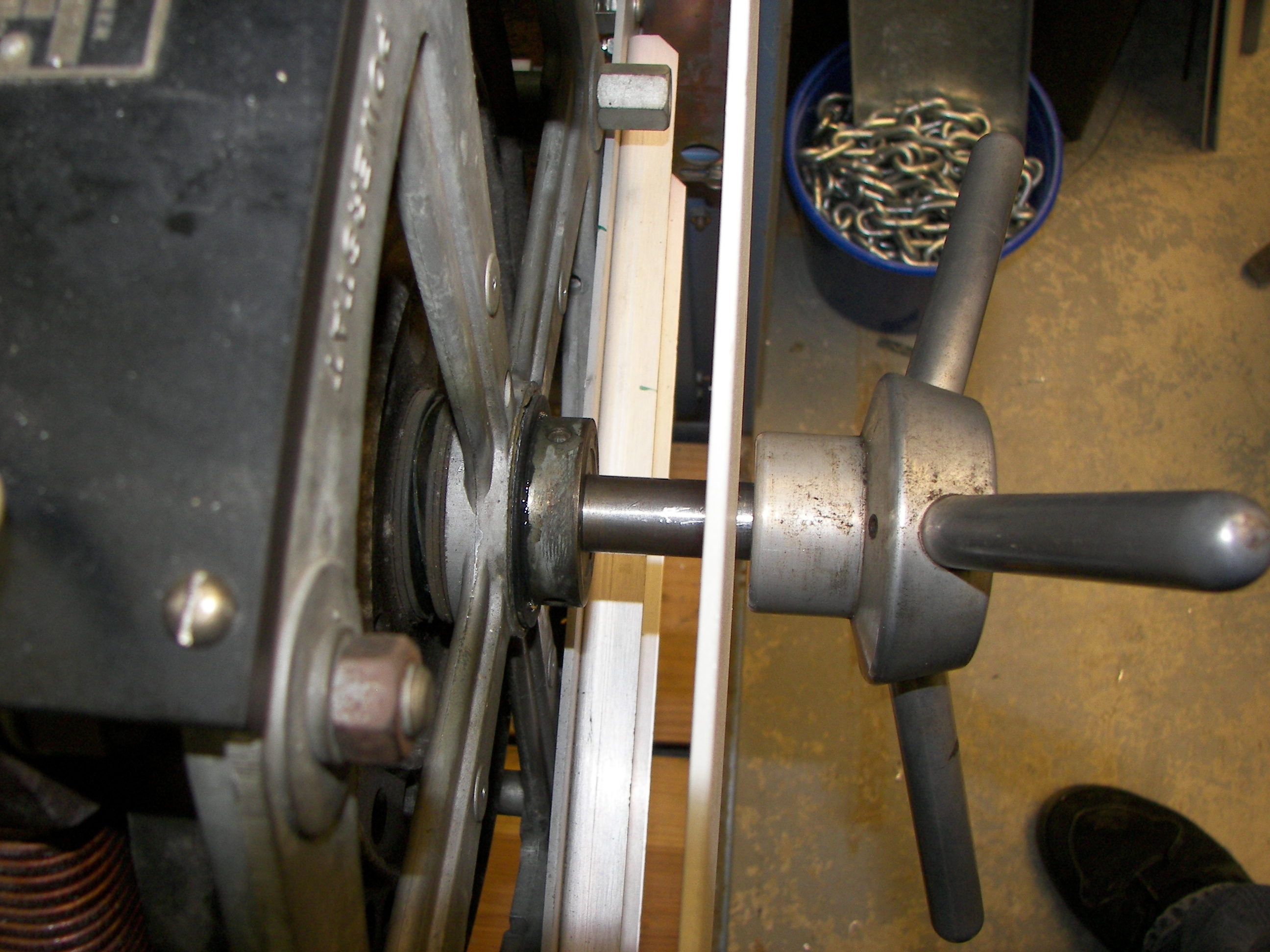
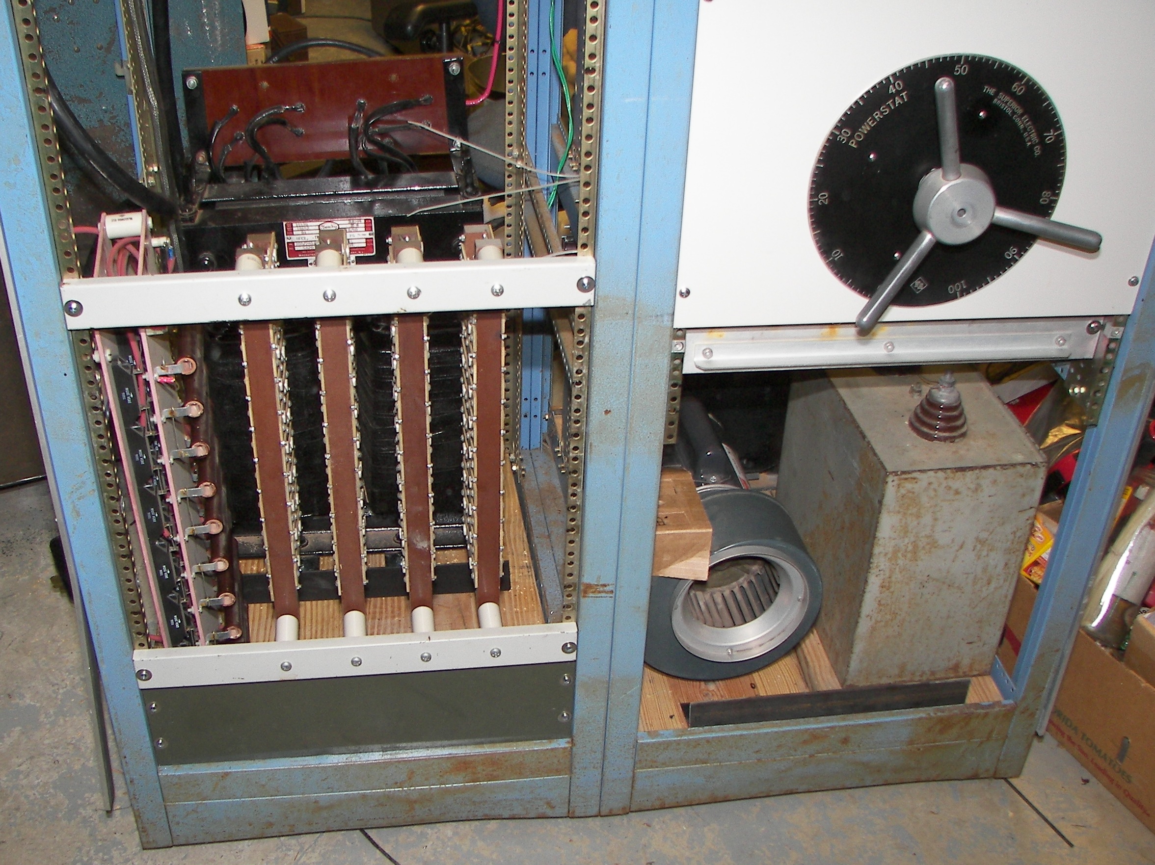
The Powerstat was originally set up with the sections in series for 460V 28A. It is made of two 230V 28A sections and can be rewired for 230V 56A by putting them in parallel which is the more common arrangement. I have to find a balancing coil for it. I like the unique handwheel on this one. It has some burs on the inside making it hard to slide on the shaft so some filing might help. The Powerstat has a Ward Leonard 600 Ohm potentiometer on the main shaft. It's rated 600V and 2.62A t0 0.4A. I think this means 2.64A max and 0.4A when the whole element is used but it's not clear. There is a concentric 1/4" shaft running through the main shaft and an Ohmite 50 Ohm 2.12A potentiometer at the very back. The shaft can't protrude because the handwheel is not on all the way due to the shaft burs. There is supposed to be a big knob on the front for the Ohmite, but it has not been found yet. The Powerstat has to be moved forward. its not mounted yet. Need to replace a missing nut run a die over one damaged bolt head on the front. |
The large Ward-Leonard potentiometer can be seen here. |
Real amplifiers have handwheels. |
|
|
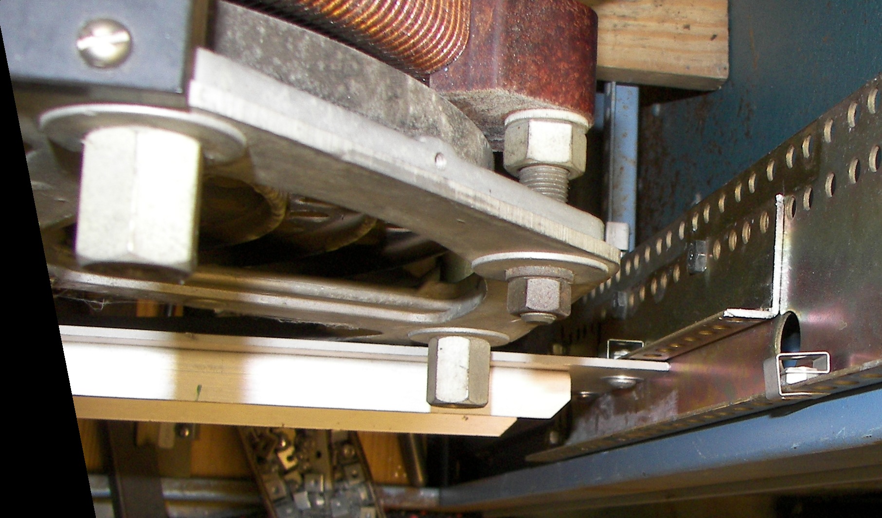
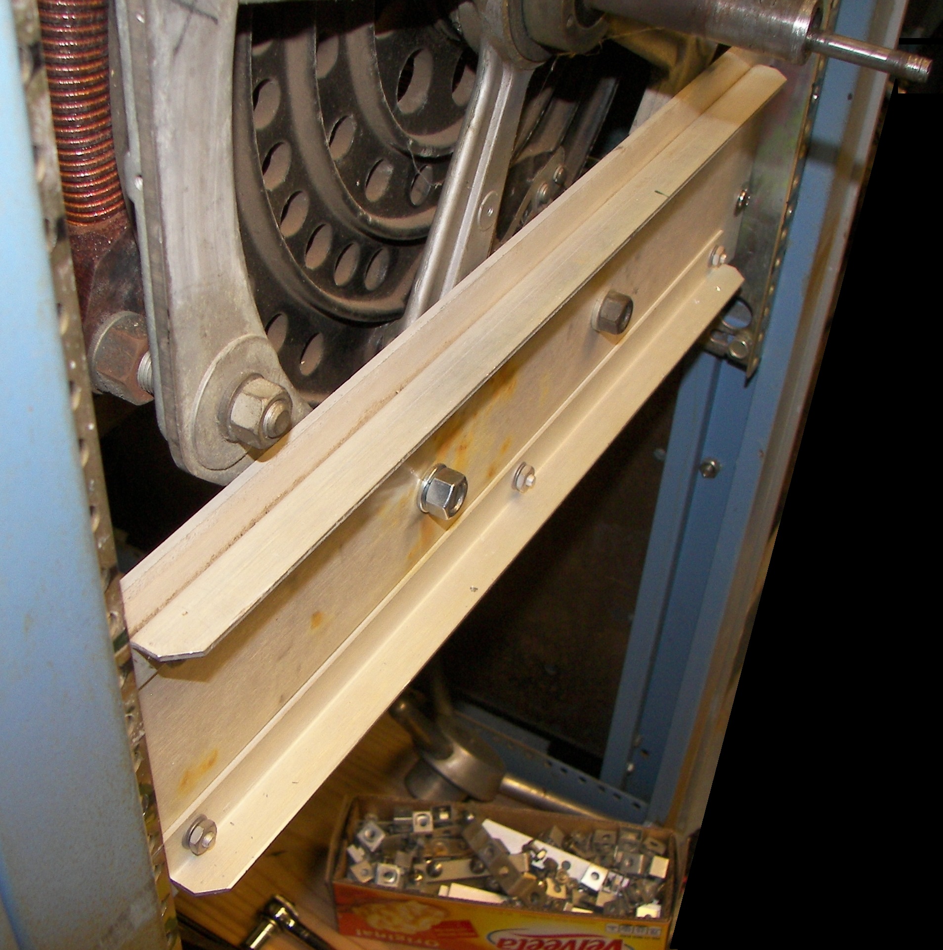
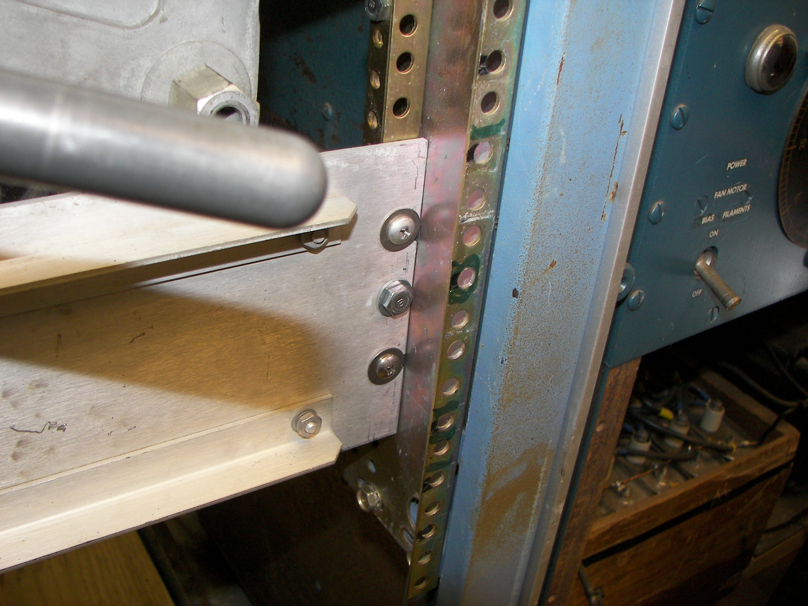
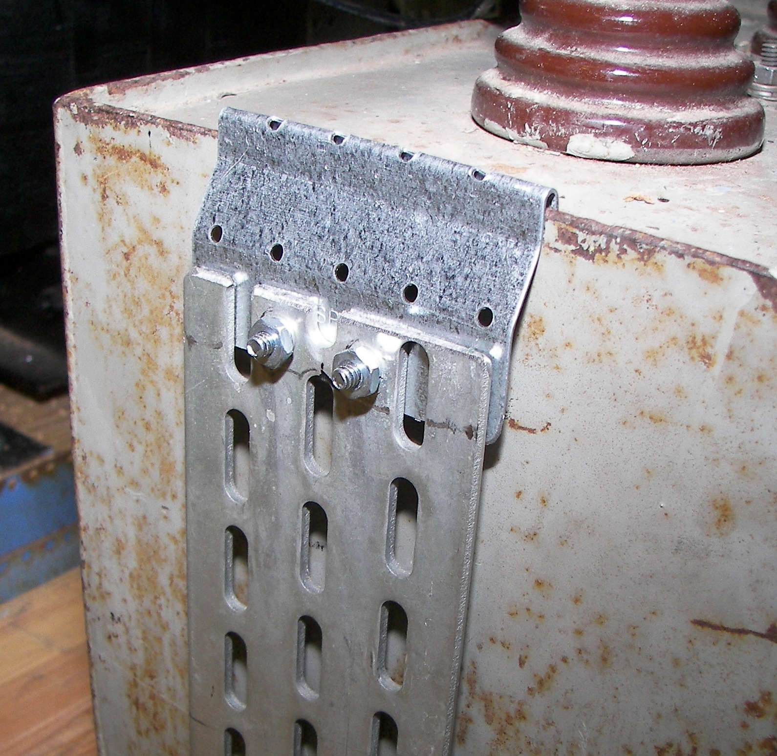
The Powerstat was recessed from the front rack panel to make a closer fit between the handwheel and panel and to avoid having many large bolts appear on the front panel of the amplifier. A 19" panel with reinforcing angles just happened to be on hand and was perfect to carry the front of the Powerstat. Some spare sections of rackmount rail were cut and installed to mount the support panel. It is first attached by just four 10-32 rack fasteners, and later two 1/4" bolts were added. |
|
Perfect fit! |

|
1/4" fine thread Grade 5 bolts added. |
|

At this point it is worthwhile to talk about fasteners. Never, ever use grade 2 bolts for something like this. It is worth the few extra dollars to use at least grade 5. Grade 8 hardware is best but cost more. Note that some hardware does not have the lines but a code indicating the grade. Always buy from a reputable source. I've had the heads on 1/4" grade 2 bolts twist off while tightening. A 1/4" grade 5 bolt has a shear strength of >3500 lbs. |

As for making the Powerstat level, no level is necessary. The level is the rack. The front and back of the top of the powerstat were compared to holes in the rack using an old panel as a carpenter's 90 degree angle. So yeah this is level front to back with the rack within about 1/32" |
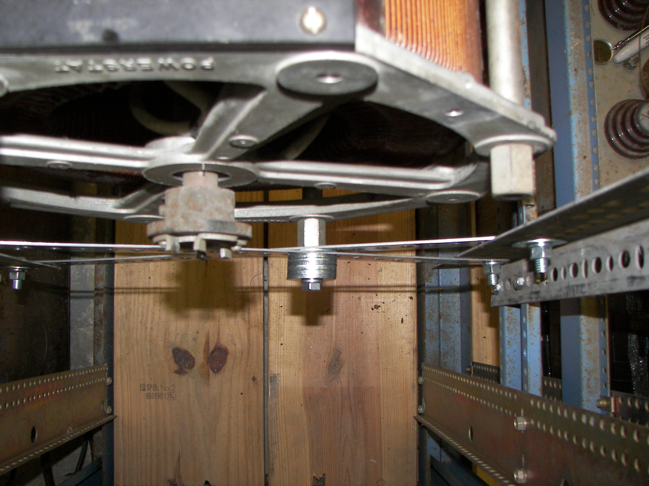
Mounting the back of the Powerstat was an interesting exercise. A thicker angle iron could have been used such as the side supports at the rear, but it was as well to use the flat metal because all the holes lined up well and 3/8" hardware was used between the X braces and the angles. the angles were fastened to the rack by 1/4" hardware, and believe it or not the holes did line up nicely. Where a bolt head or nut was small compared to the hole (some oblong holes) in the angle, a large fender washer was used to provide a flat surface. The front to back fit of the angle iron position vs the rear of the Powerstat "big hexagonal nuts" just happened to be perfect. One flat strap was placed upwards left to right on the front side of the angle and the other was placed downwards left to right on the backside. These had to come in and out a few times to trim the ends at angles for a good fit without sharp triangular tabs protruding into the next space, or just to make them fit inside the angle. These little details consumed much time. |
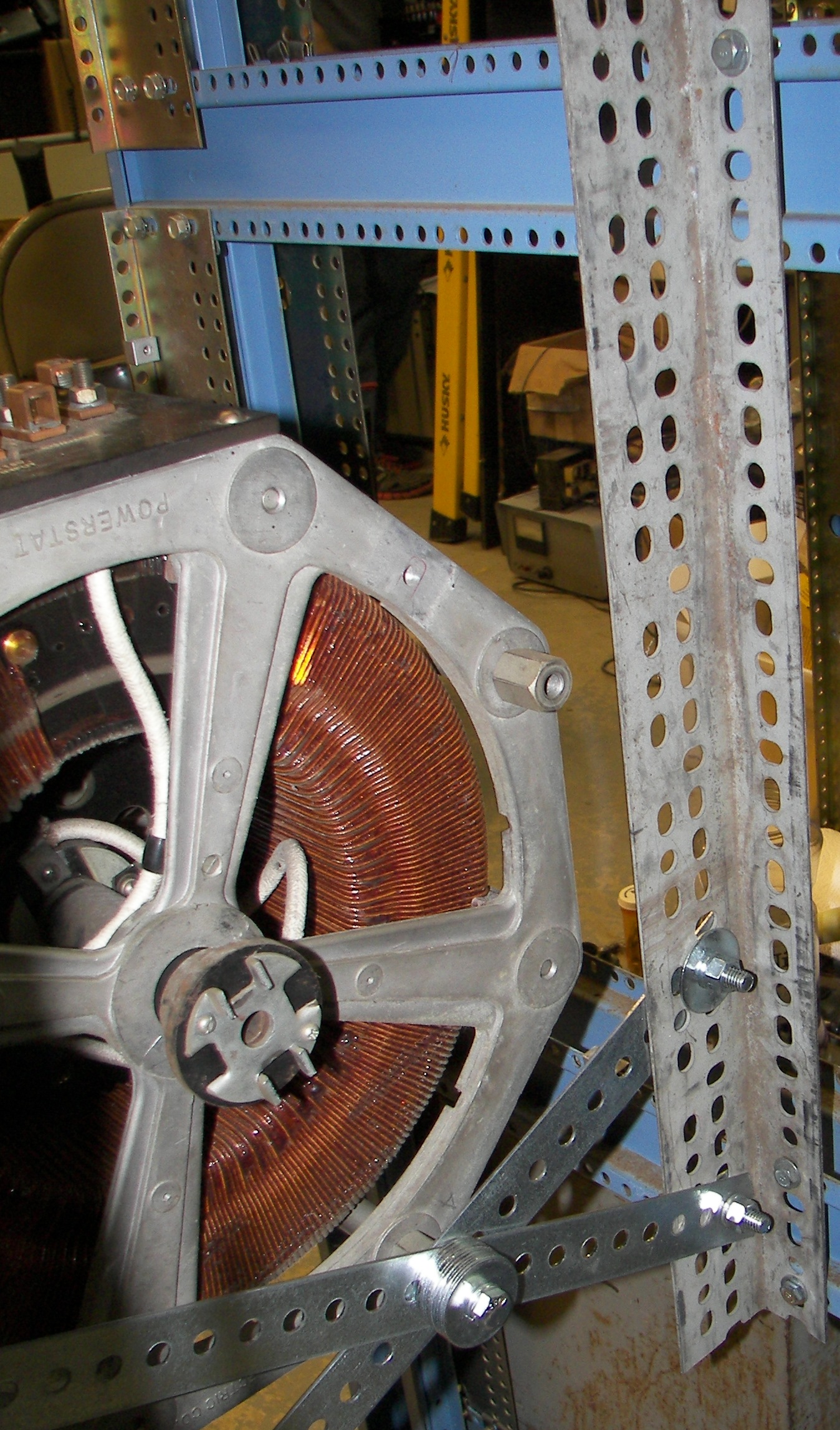
It may not look very strong in the back end, but the triangular arrangements here will support several times the weight. The triangle arrangement came about due to the effort to make the holes line up. A flat 'holey metal' piece was bolted loosely to the Powerstat's support spot, and rotated until there was a clear hole through both at each end. The ability to stare at something until the imagination calls a few simple solutions to mind is useful. The only funky part is the stack of washers taking up the space between the 3/8" bolt head and the big hexagonal nut. A shorter bolt and Another brace connecting to a different Powerstat bolt should be added later. |

|

Very Nice! |
|

The power cable, temporary at least, is #8. It is rated 55A. |
50A plug. Typical 'clothes dryer' type. |
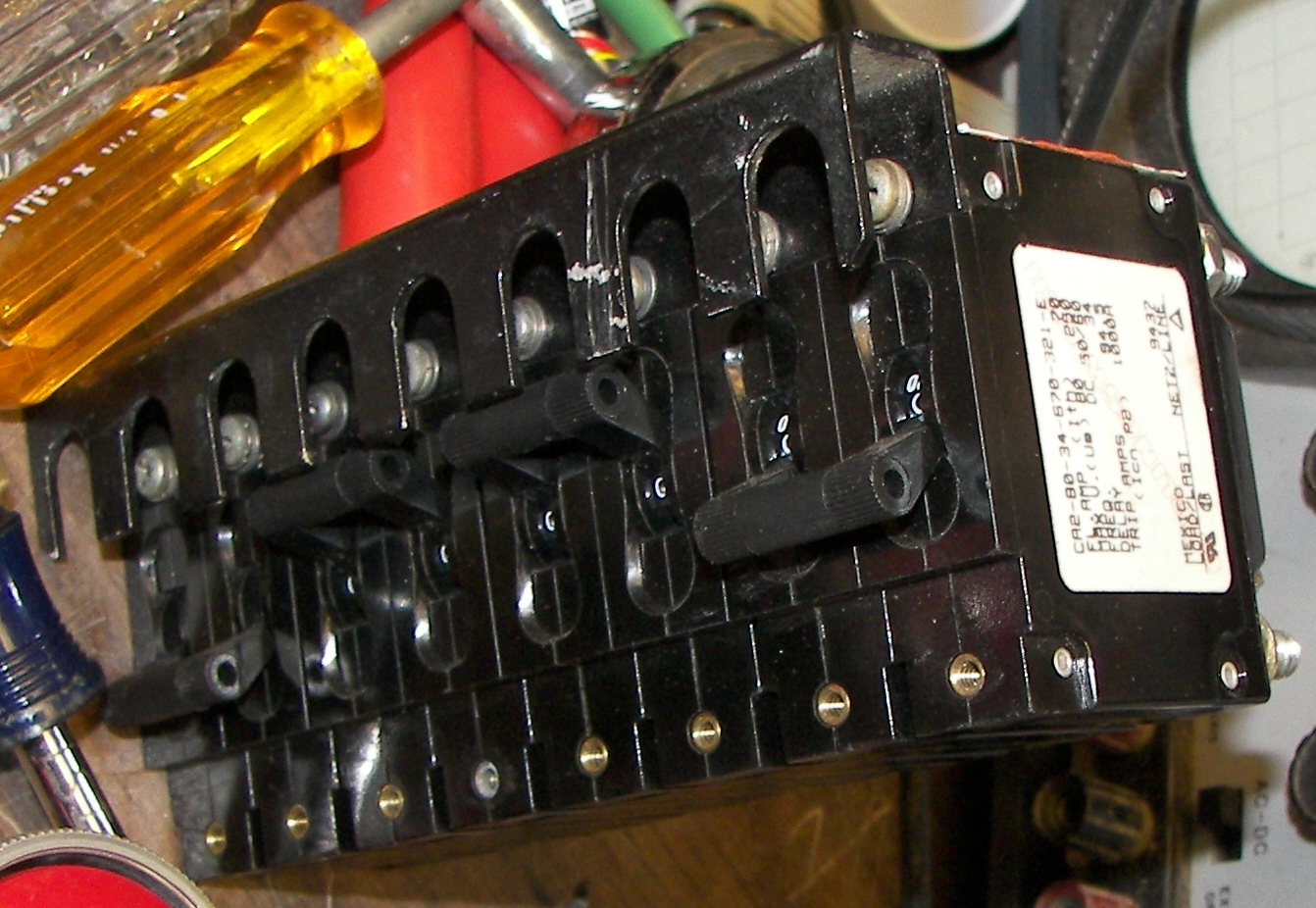
Magnetic circuit breakers are fast and avoid having to replace fuses. All high currents are switched by contactors so that the only time a magnetic breaker gets any real wear is when tripping on overload. This allows the breakers to be used as the amplifier's power switches that only energize contactor coils and small loads. The contactors then apply the large loads only after the breakers are closed. I believe this arrangement is reliable. Anyone interested is invited to check the control circuits in the schematic. Even so, they are rated to use as switches - 10,000 operations at rated current. |
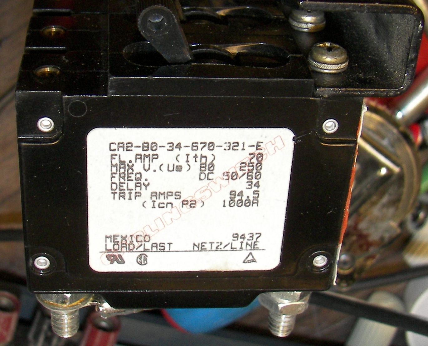
These purely magnetic breakers have a resistance of about 0.003 Ohm yet on a dead short (12x current rating) trip in 4-5ms. These have 3750VAC insulation between pole and the operator. AC Short circuit capacity is 5000A when backed up with a UL LISTED Type K5 or RK5 fuse not to exceed 175A. (well that is much more than the relatively slow thermal+magnetic residential 50A breaker in the wall panel. |
|

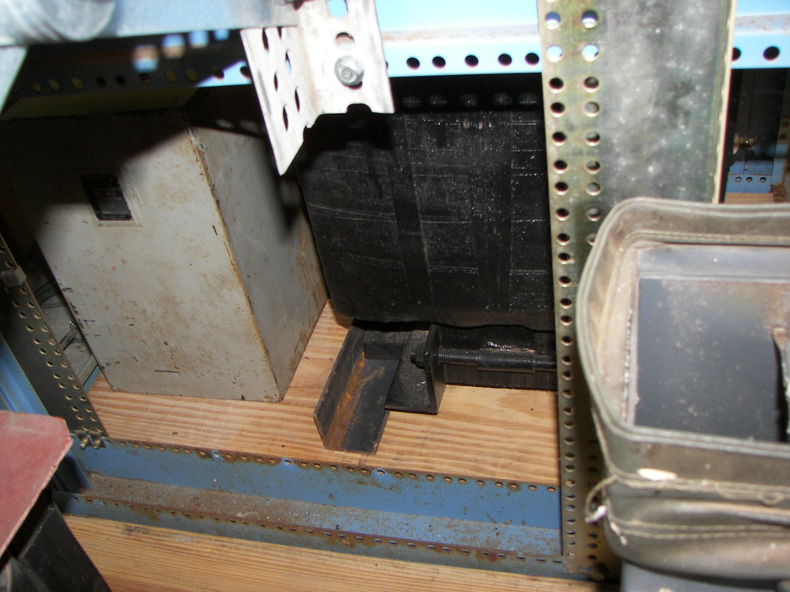
The lower grating there was removed as it was too close to the Powerstat terminals. There is plenty of wiring access from behind the breaker. Like the panel and breakers, almost everything in the project is repurposed from something scrapped. |
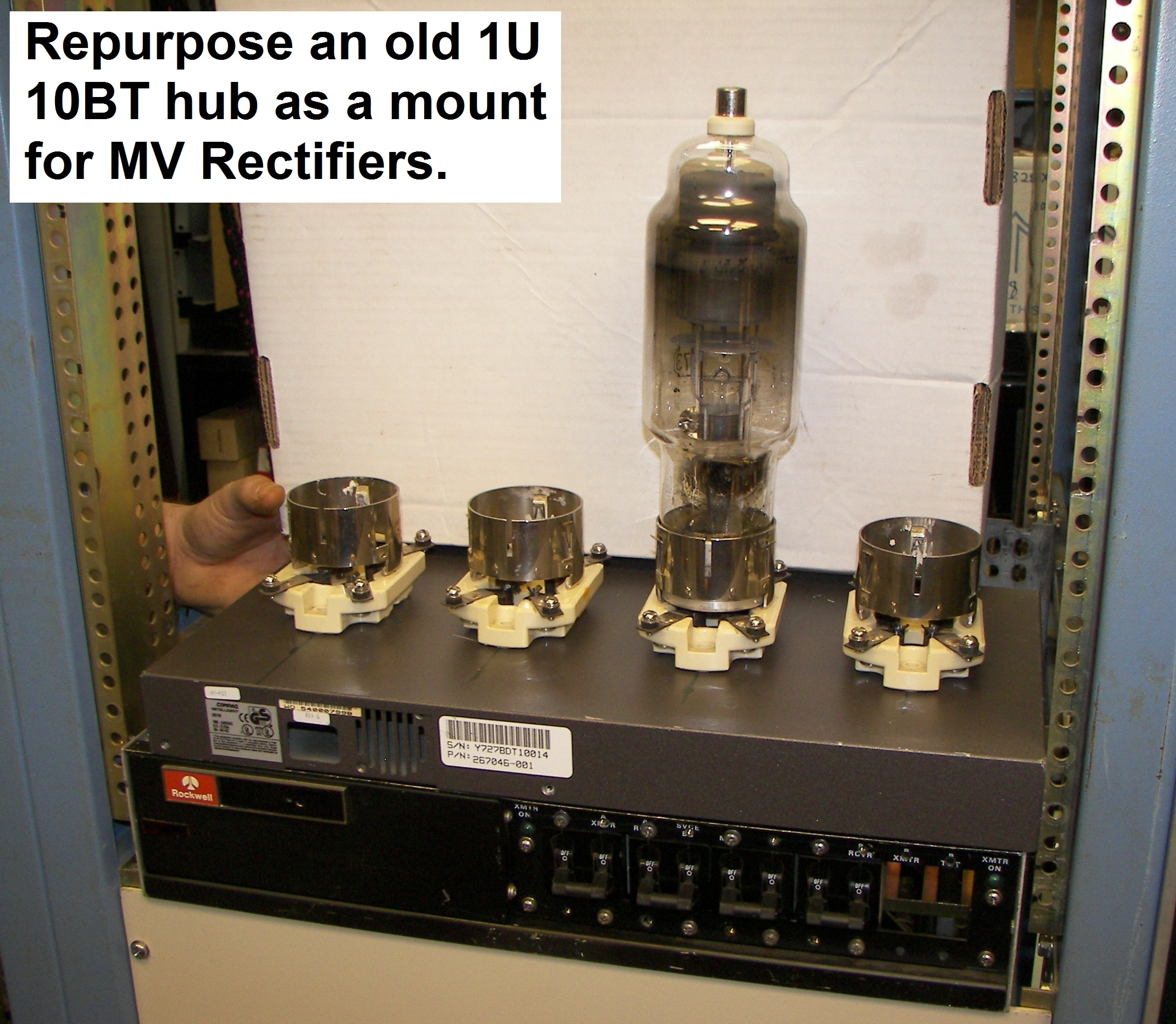
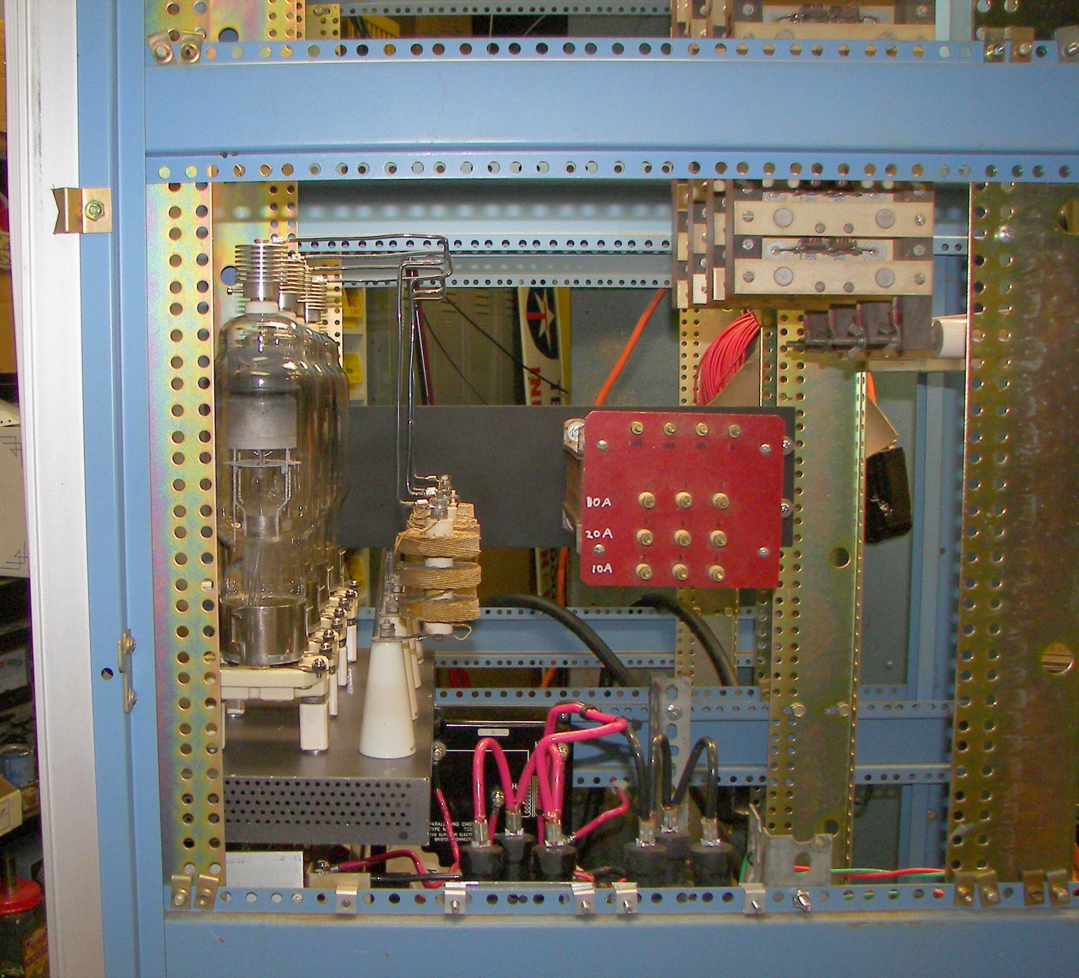
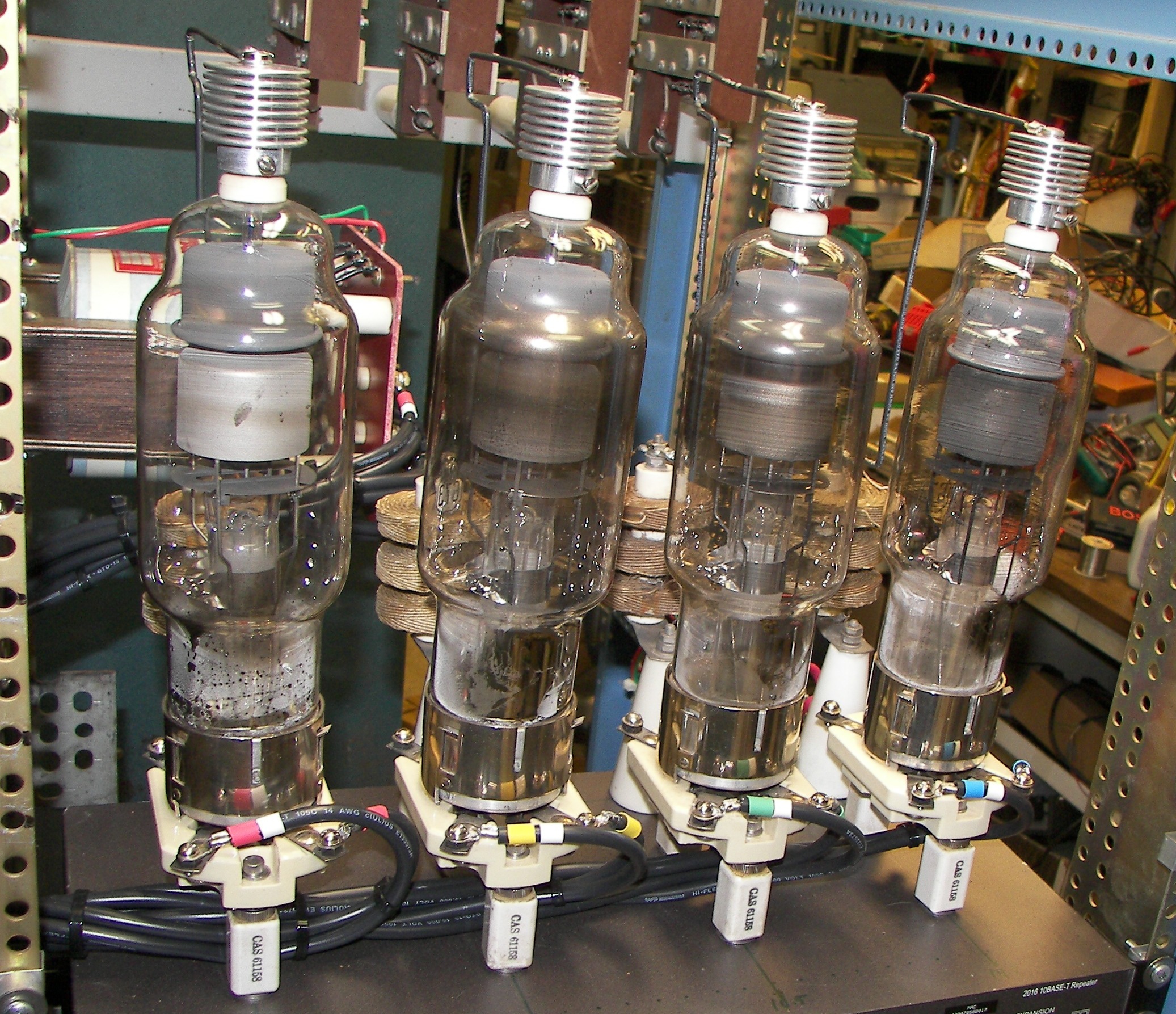
Since the 3CX3000A7 does not glow like tubes of old days, the rectifiers are up-front and will be behind a piece of UV-blocking glass so their beautiful glow can be enjoyed. |
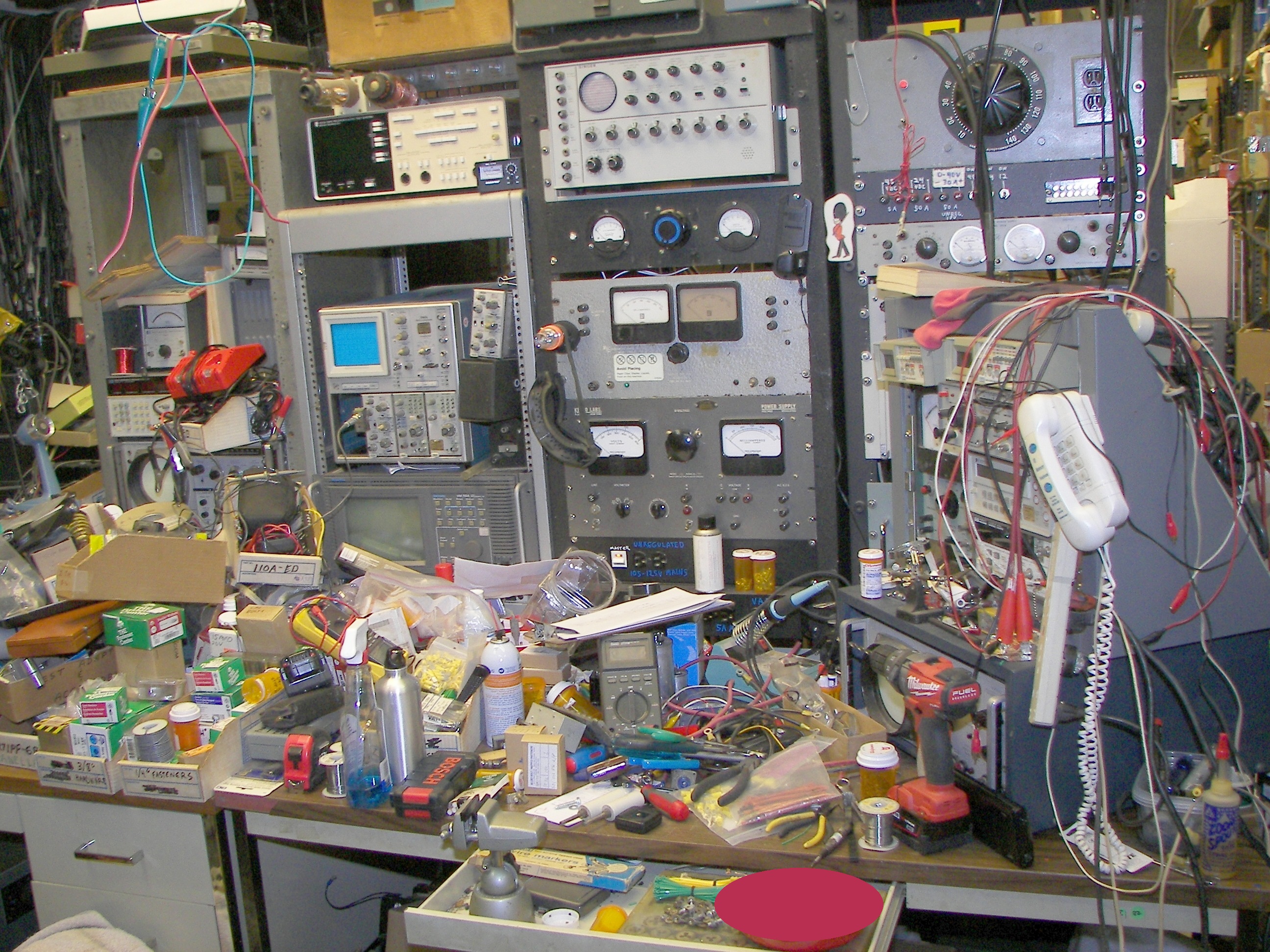
"Junkbox" amp does not mean cheaply made parts. Nothing but the best here. |
|
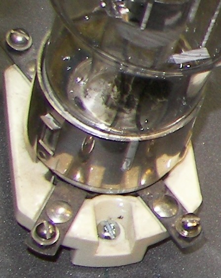
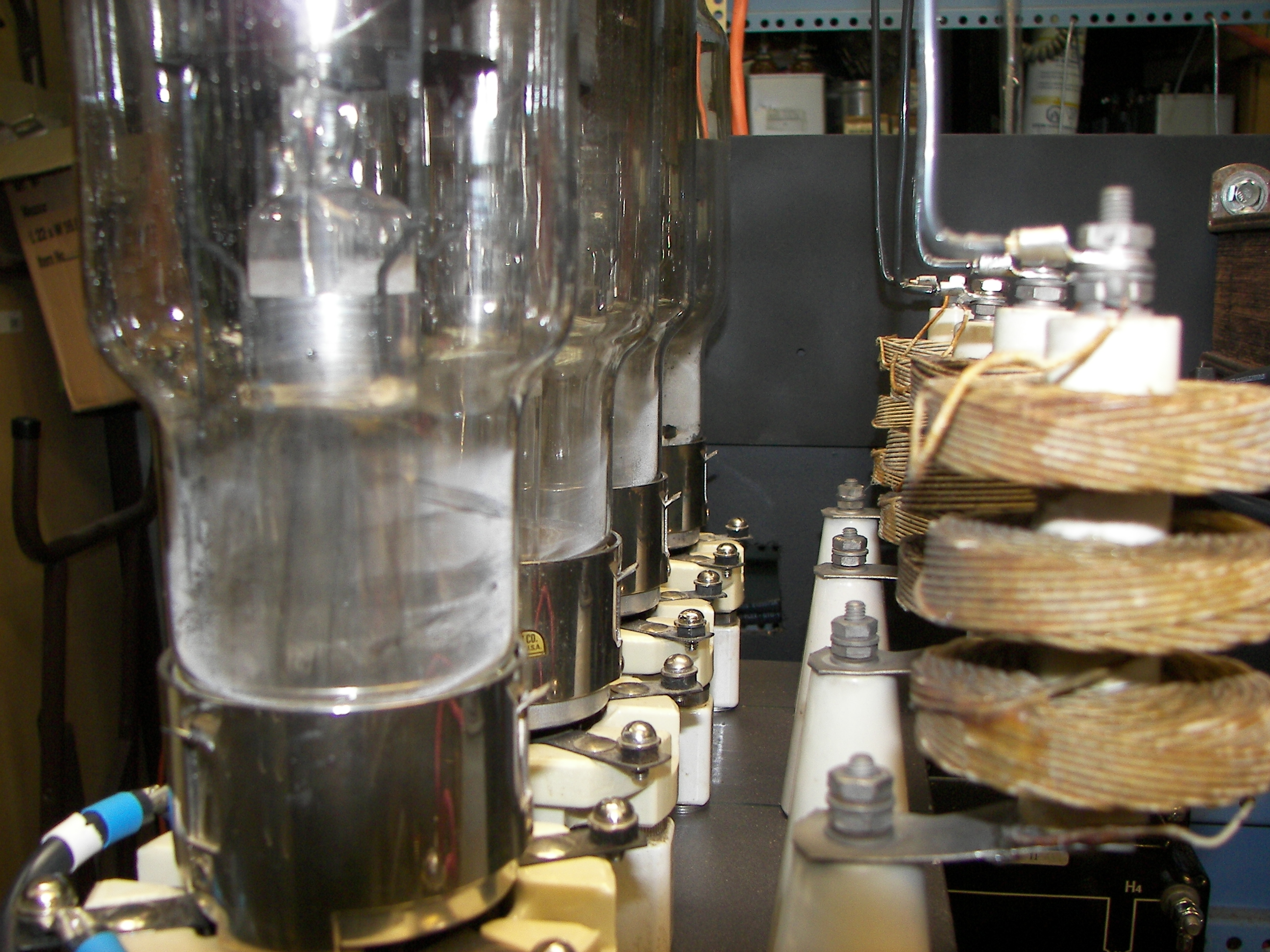
These new sockets and there are as-new type 673 Mercury vapor rectifiers. |
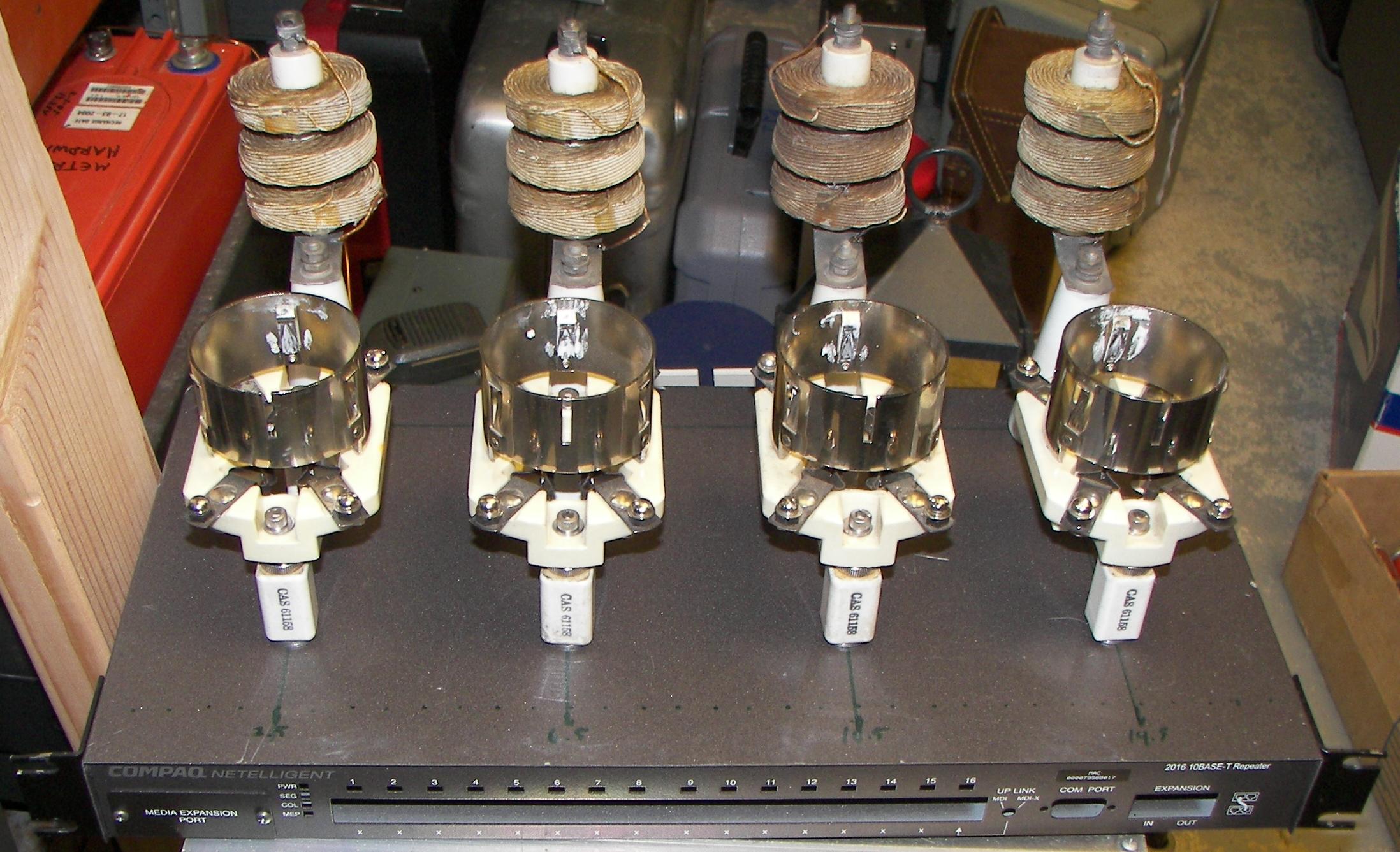
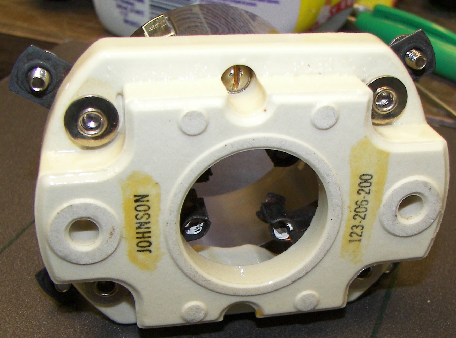
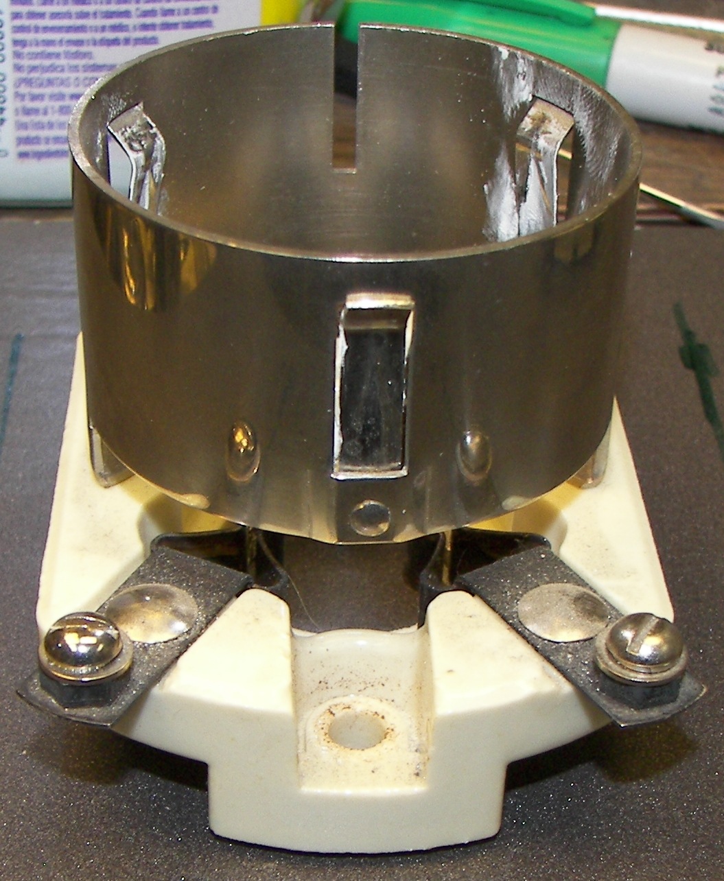
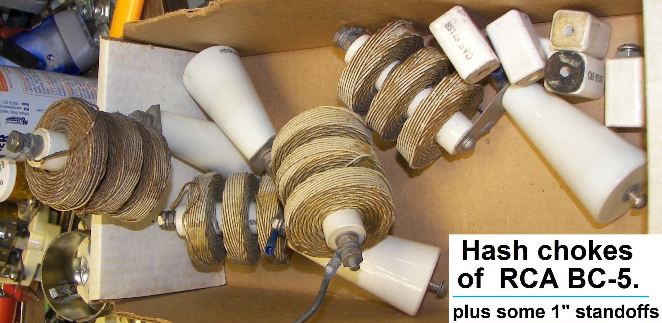
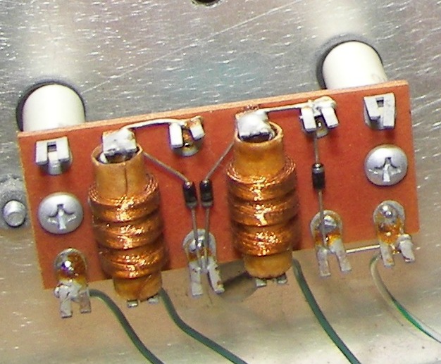
The rectifier sockets are raised on 1" ceramic insulators since their terminals can have up to 6500V on them. 1" is excessive for 6500V but the insulators were on hand. 1" is about the leg length on most local spiders. That was advised by someone who knows. The ceramic standoffs were mounted this way. Hash chokes from an RCA 5KW transmitter were also installed as is often advantageous with Mercury vapor rectifiers. |
|

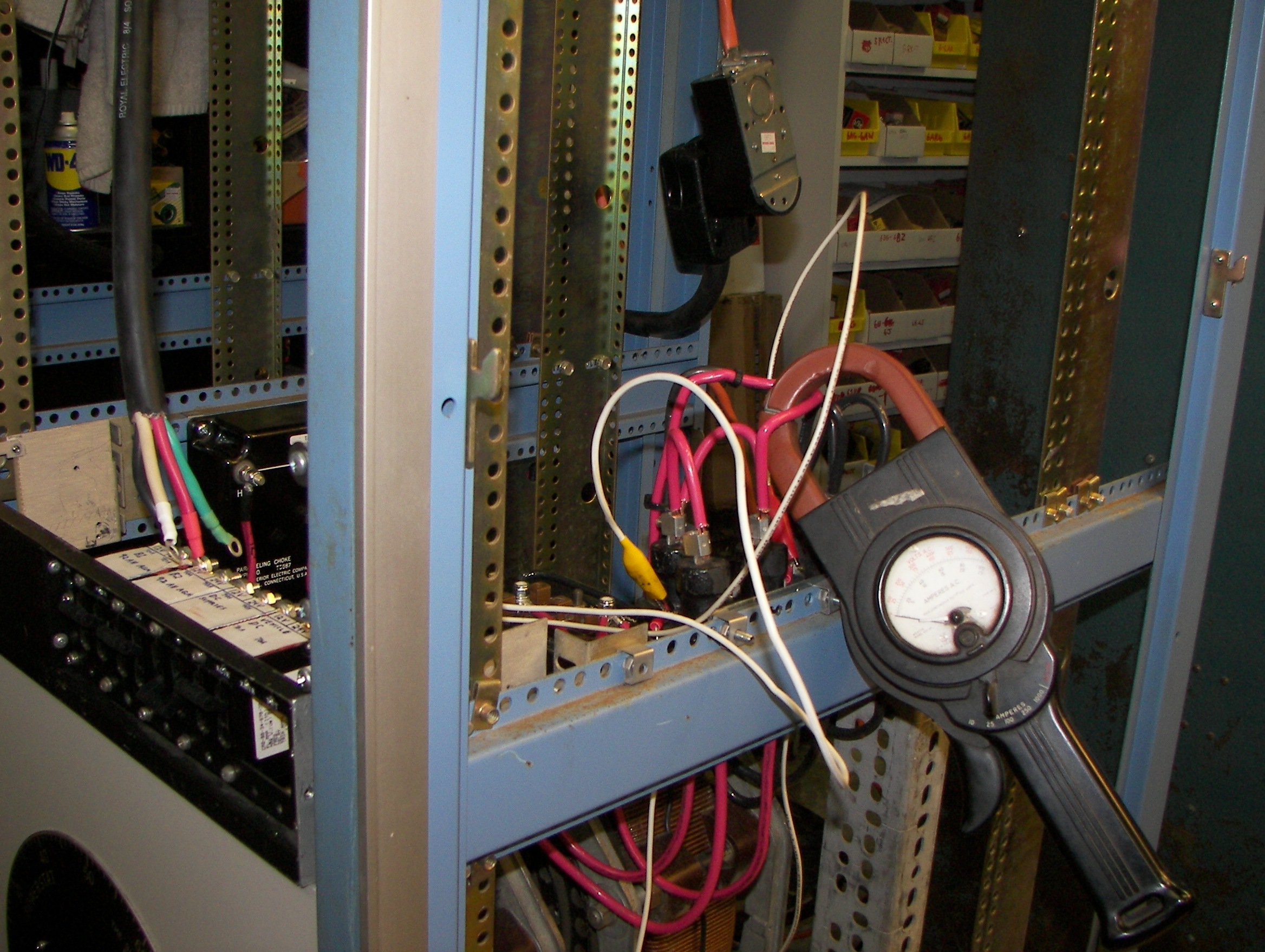
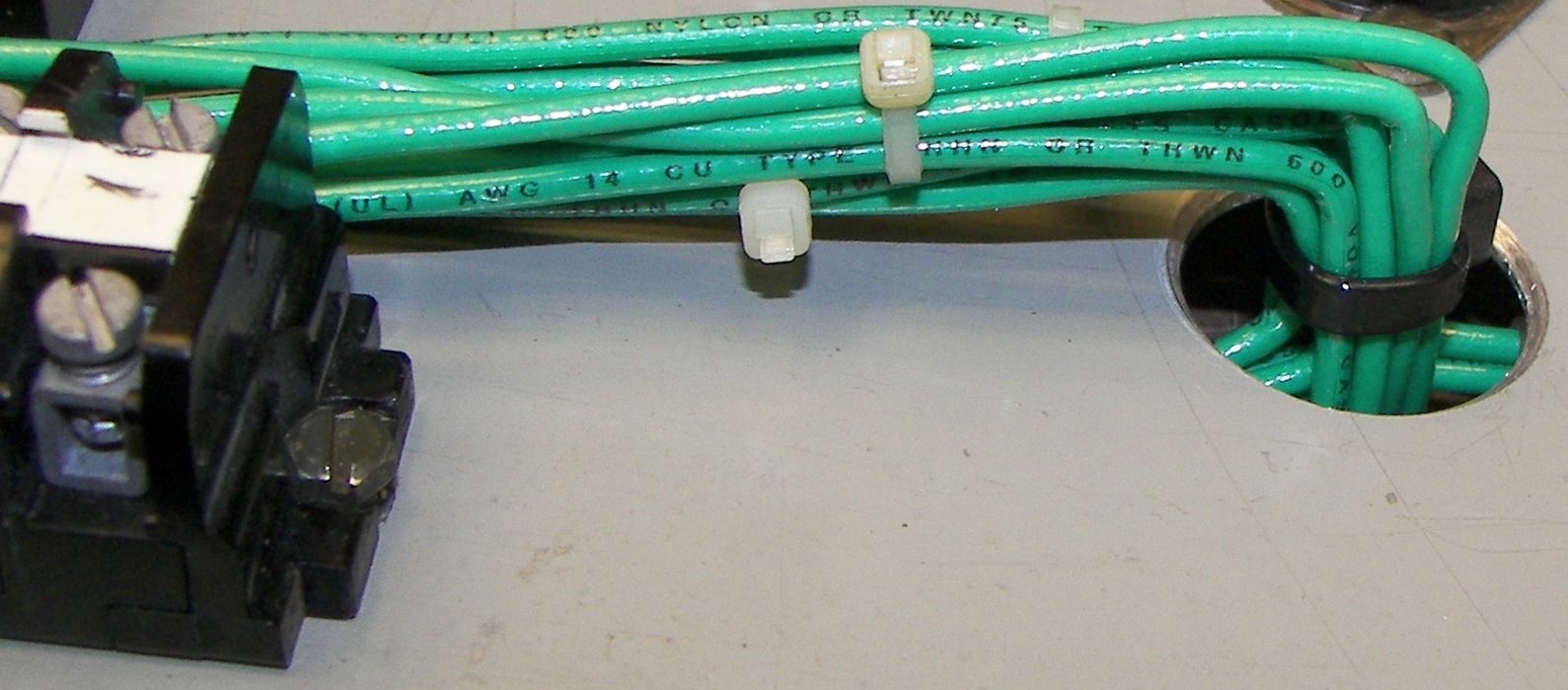
#6 THHN wire -Thermoplastic High Heat-resistant Nylon coated wire was salvaged from scrapped equipment. The insulation is polyvinyl chloride (PVC) with a nylon jacket. The nylon protects against abrasion and cuts as well as hydrocarbons. It's rated 600 volts and 90 deg C. dry and 75 deg. wet. This is used for all 240V circuits. The other wire used is mostly 600V, #14 solid with PVC insulation. |

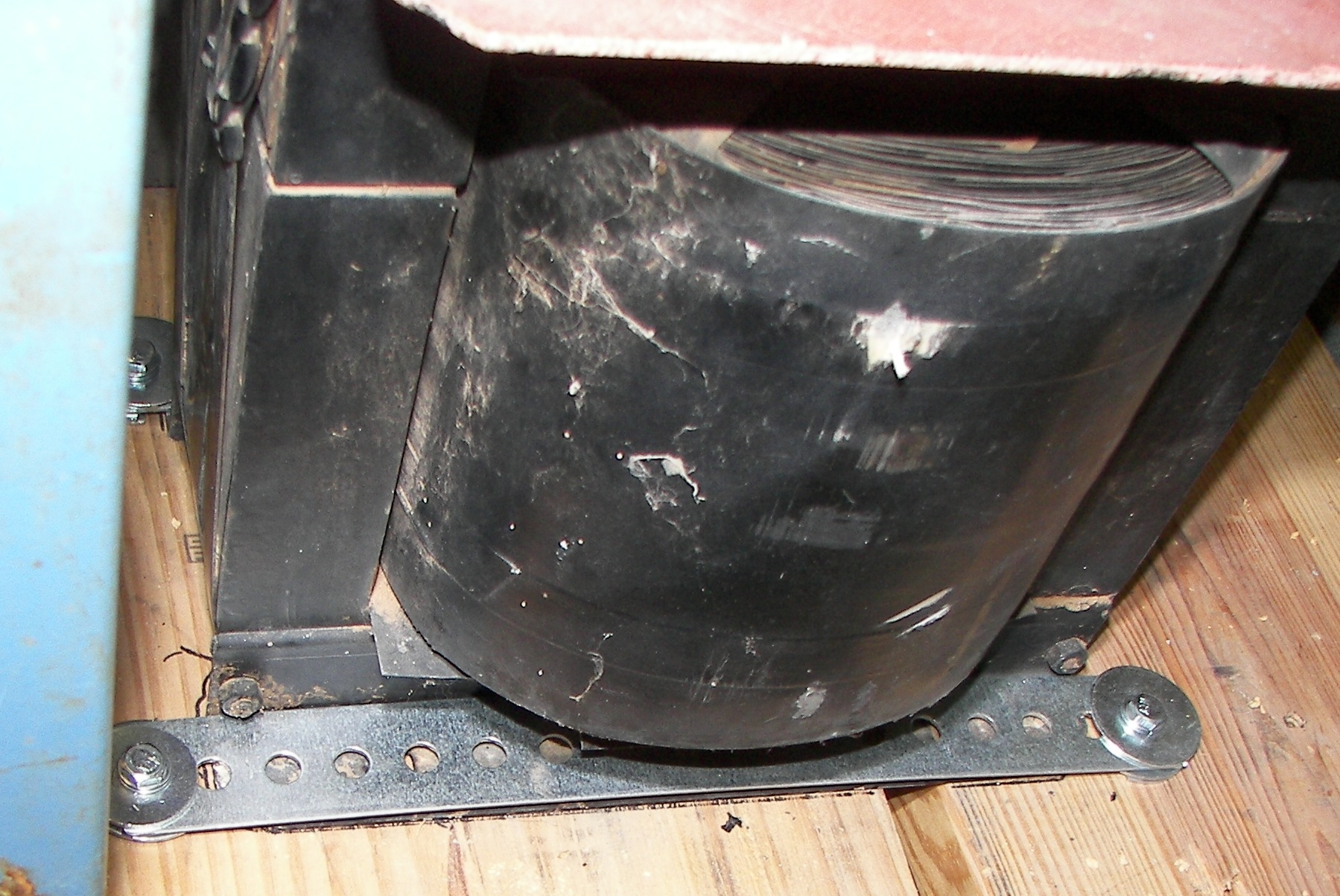
Unfortunately the original casters were not up to the weight. Nothing had been bolted in on the floor yet, so all was pulled and eight new double-wheel rollers rated 300 Lbs each were swapped in, 4 per rack. They are McMaster-Carr 9908T19. |
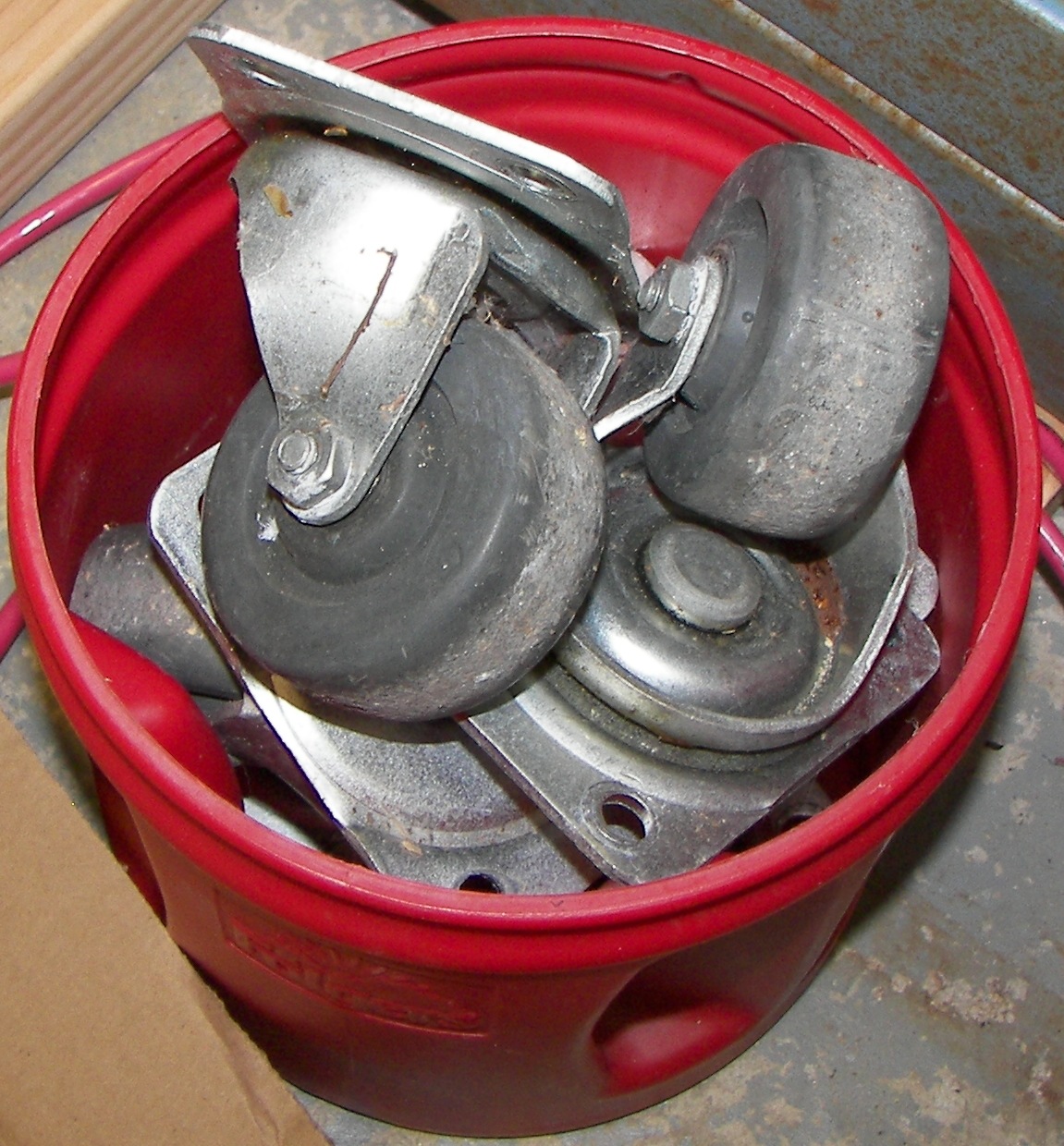
The old casters were swapped to someone wanting to make a couple of furniture dollies. They had a lot of use left in them. |
|
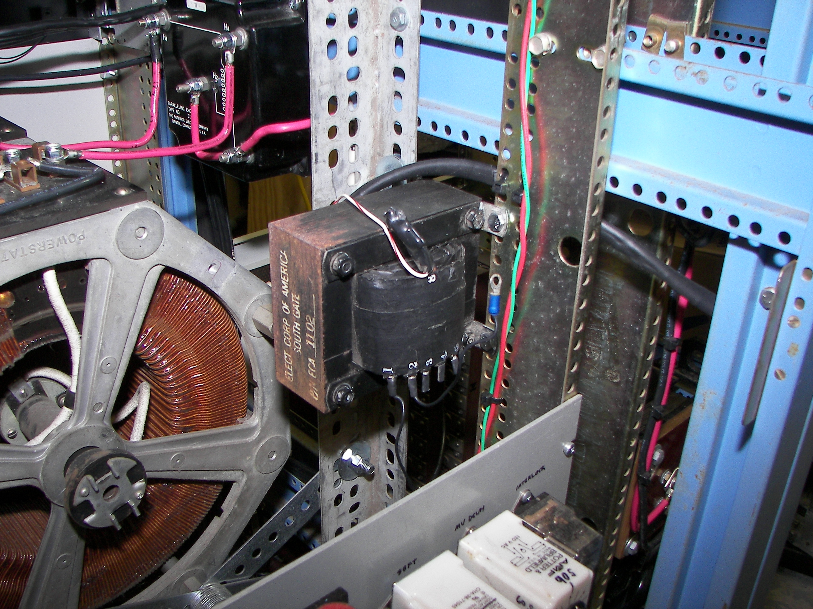
Primary wiring to the plate transformer. |
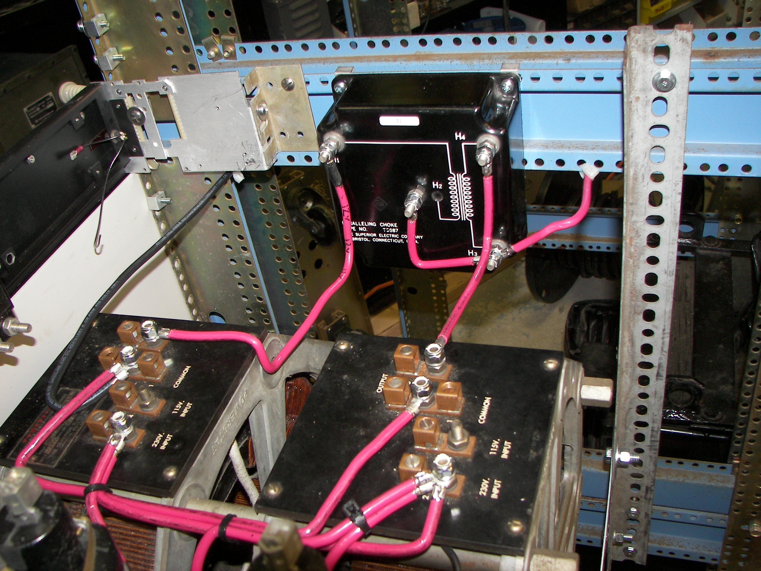
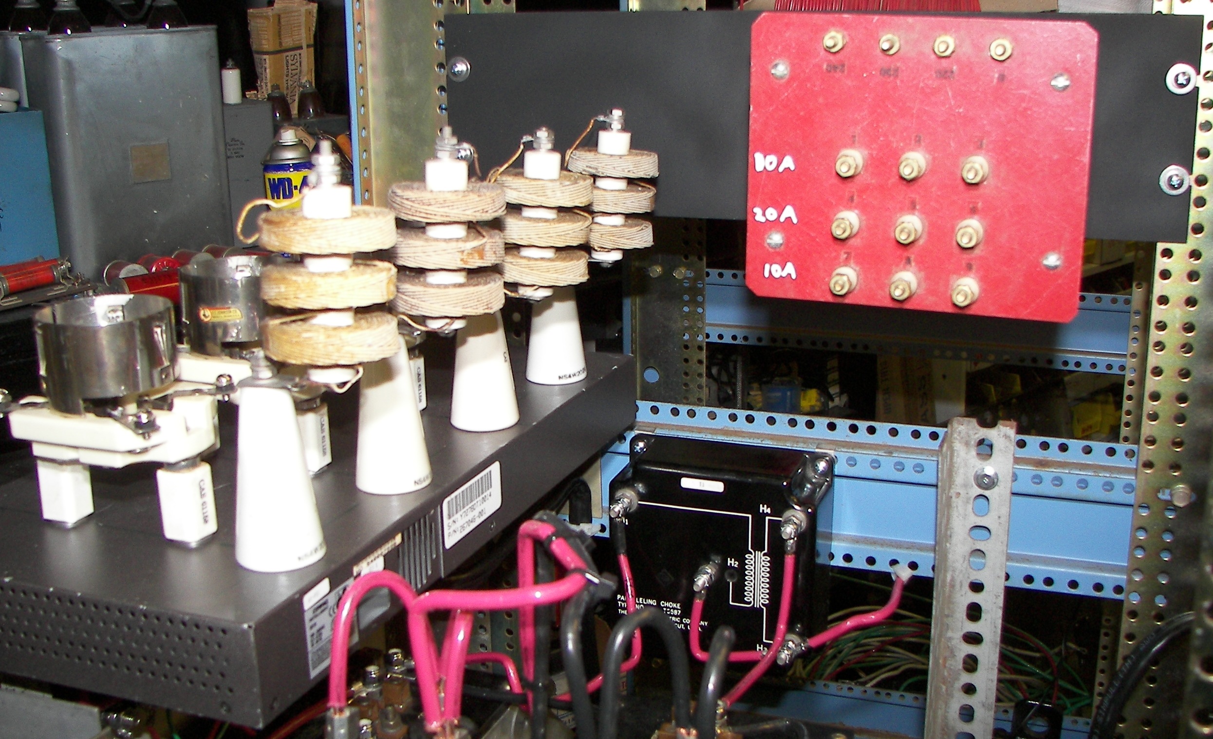
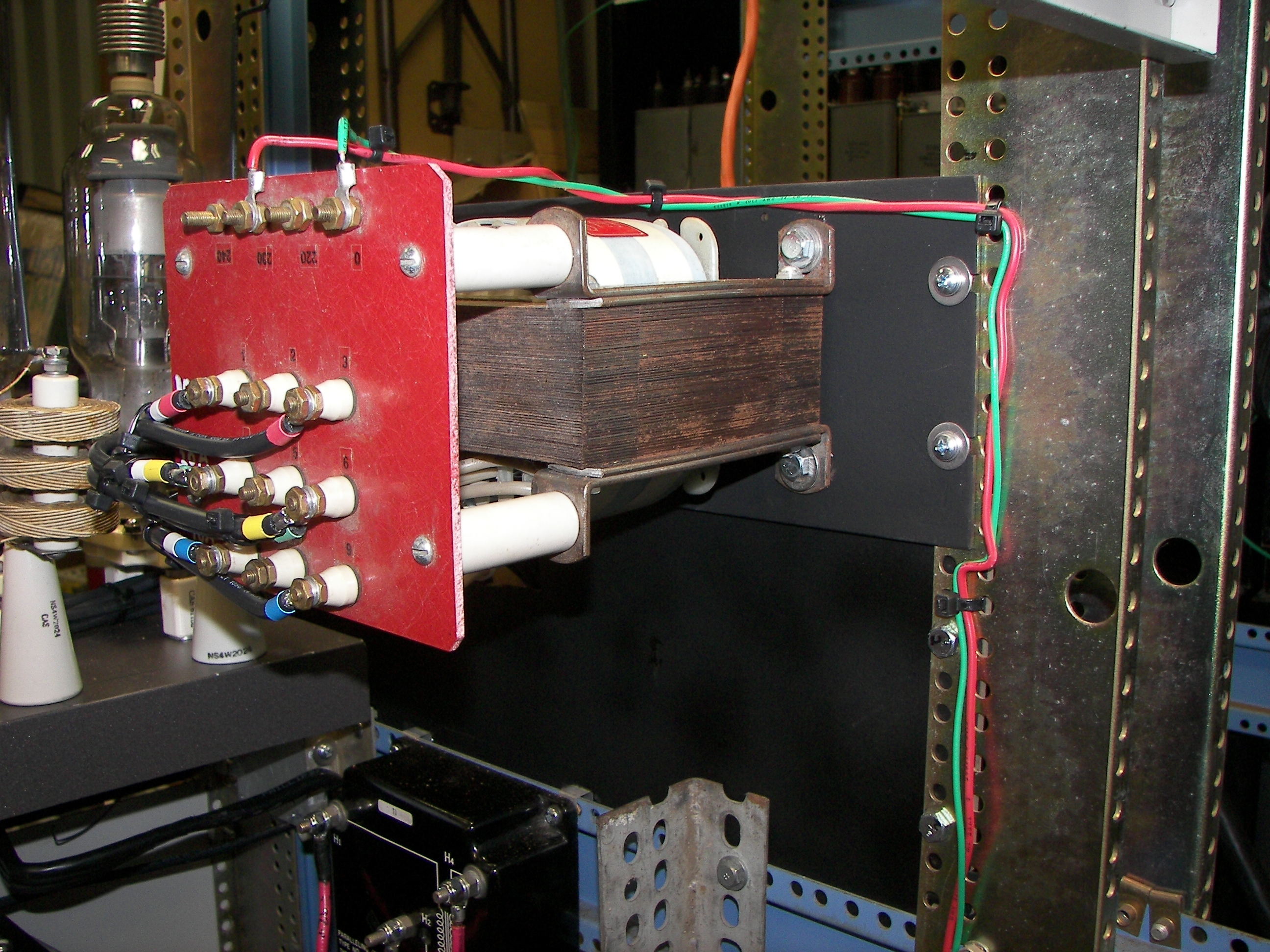
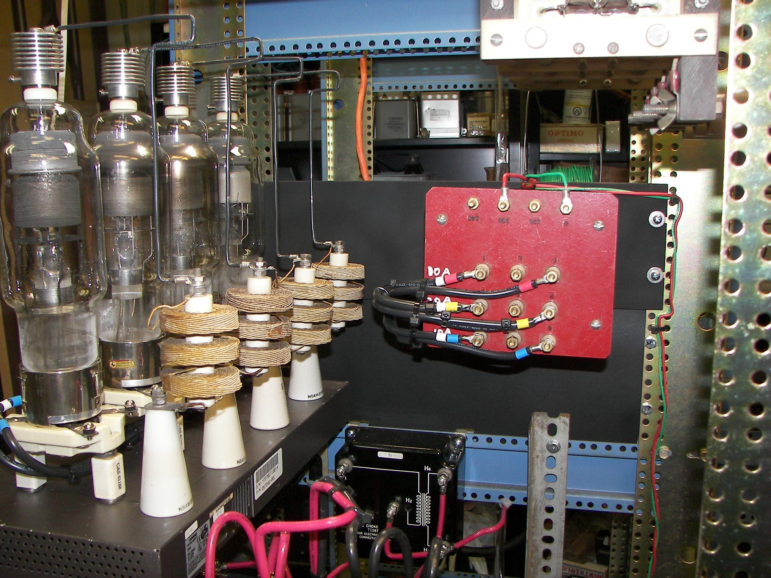
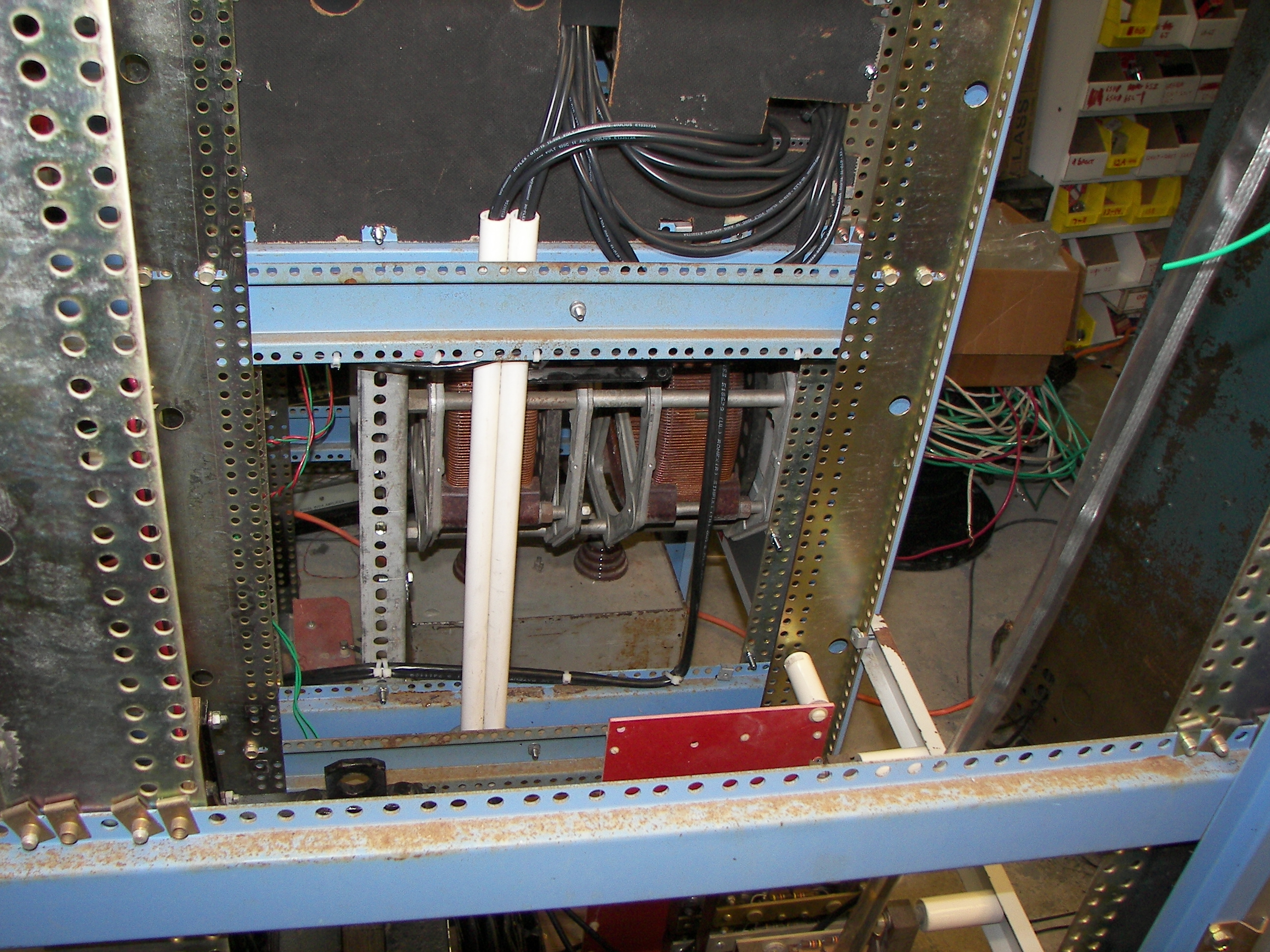
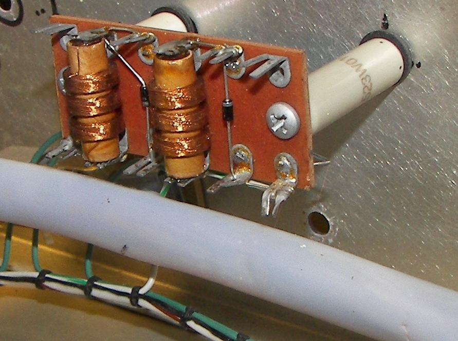
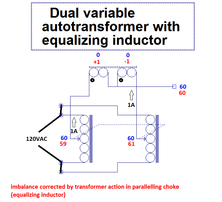
A paralleling choke is used when two sections of a variable autotransformer are to be used in parallel. It forces the current to be equal among the sections. |
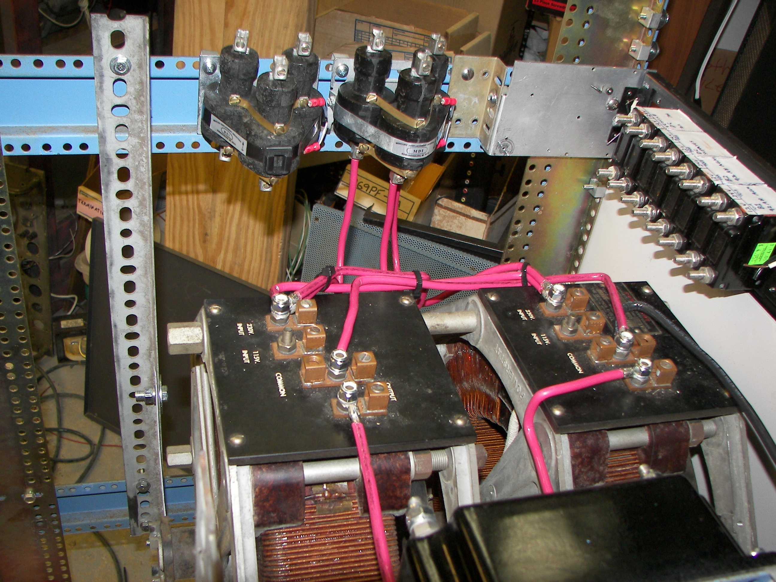
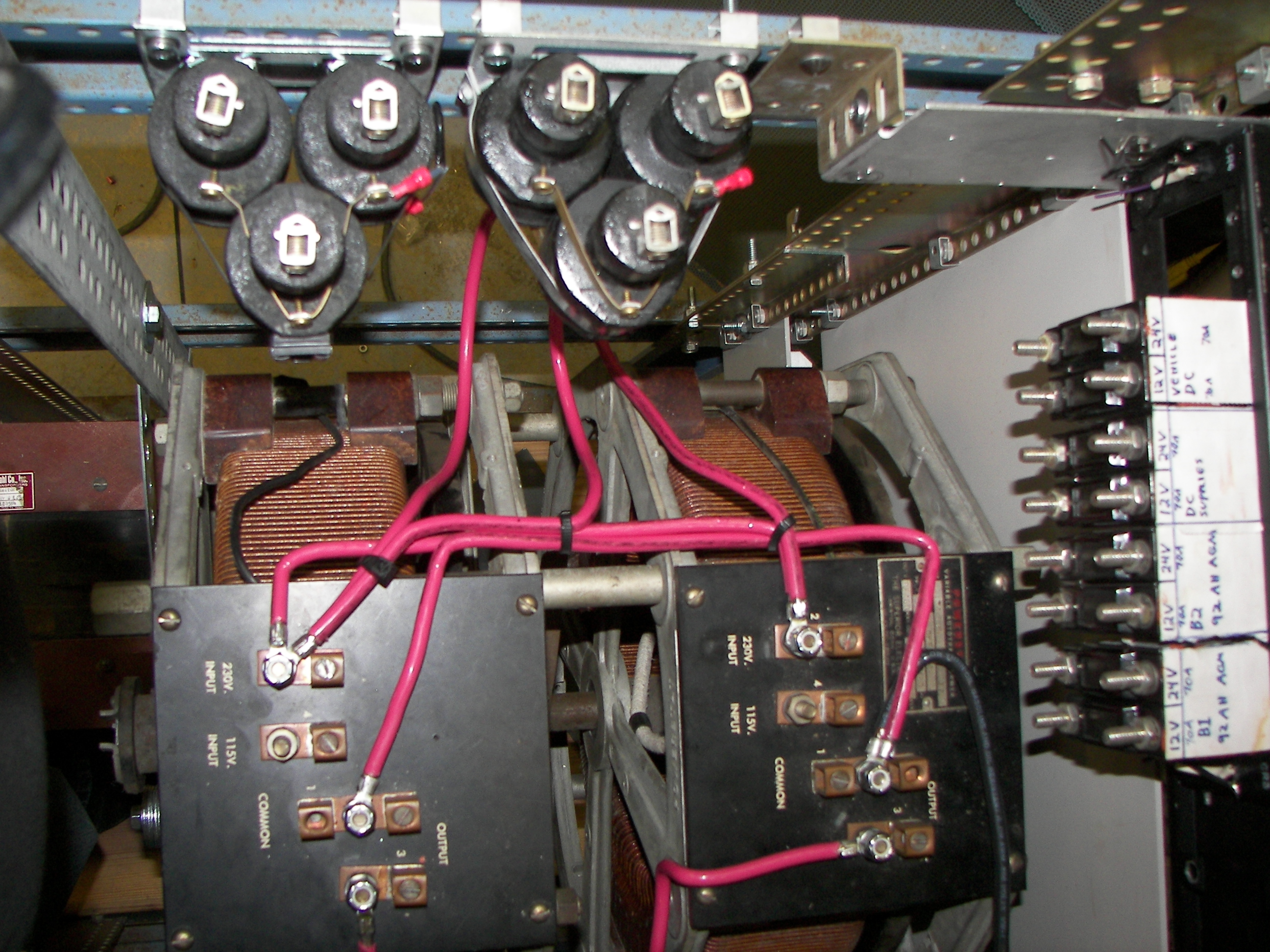
Each 3-unit Mercury contactor has its sections in parallel for 90A rating. Two are used. One is for connecting L1 and one for shorting the inrush limiting resistor in series with L2. (in any case closing the main breaker on the front panel removes all power) |
|
|
The parallelling choke. This is well-described as an anti-common mode choke. It's a two-winding transformer of about 12 turns #6 would on a 4" I.D. tape-steel core of 3/4"x3/4" section. Magnetic flux is canceled when equal current flows through both windings. When the current is unbalanced, a lower impedance load is presented to the deficient section of the variable autotransformer so that more current is drawn from it. It is not intended to remedy the effects of burned spots in the windings, but rather to correct minor differences of a couple of volts at the output terminals. When two Powerstat (or any other variable autotransformer) sections are places in parallel, a difference of only a volt or so can cause very large circulating currents to flow between the two units, resulting in an effect like a shorted turn on a transformer. The diagram shows how the voltage correction is applied |

|

|
|

|
|
|
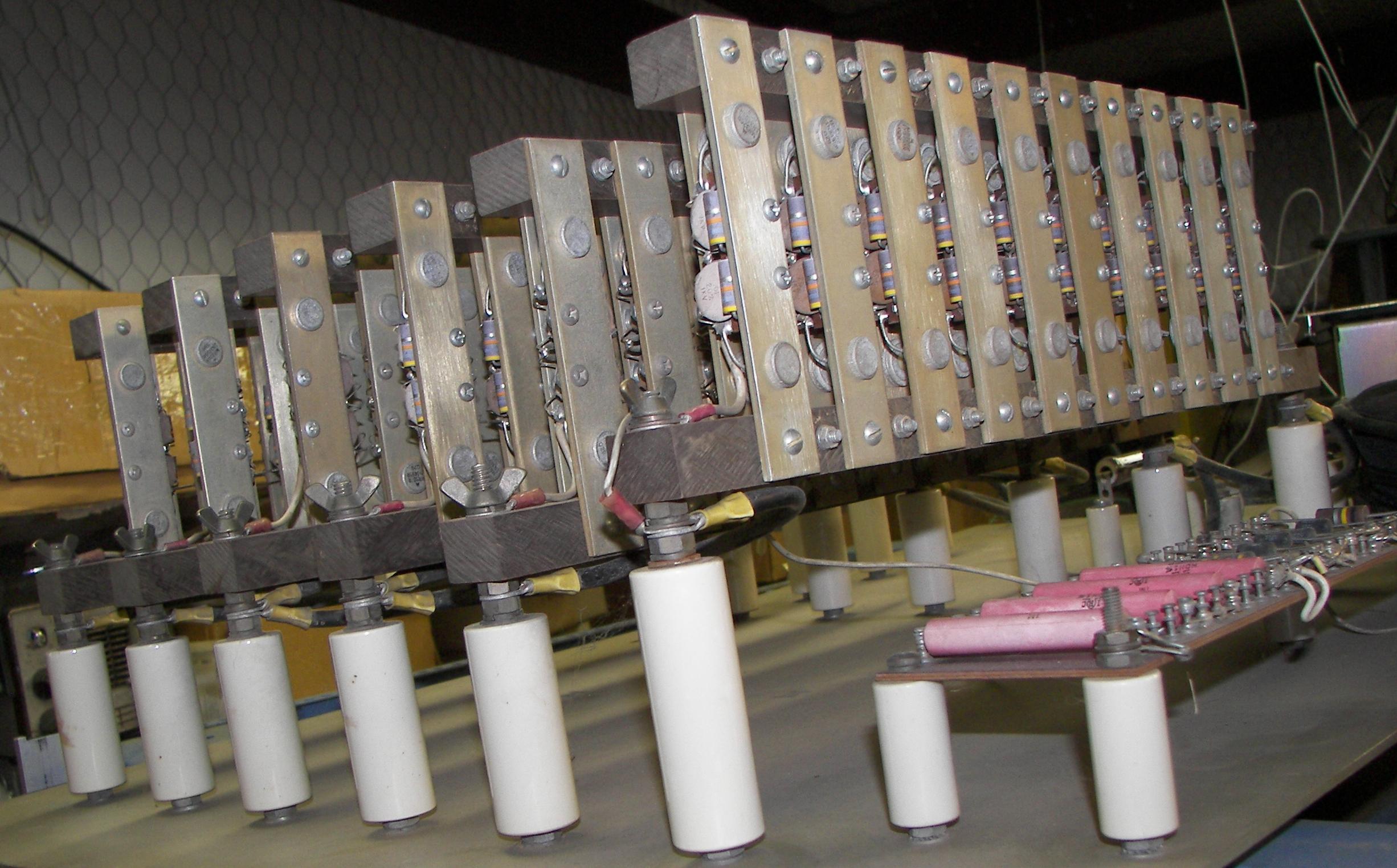
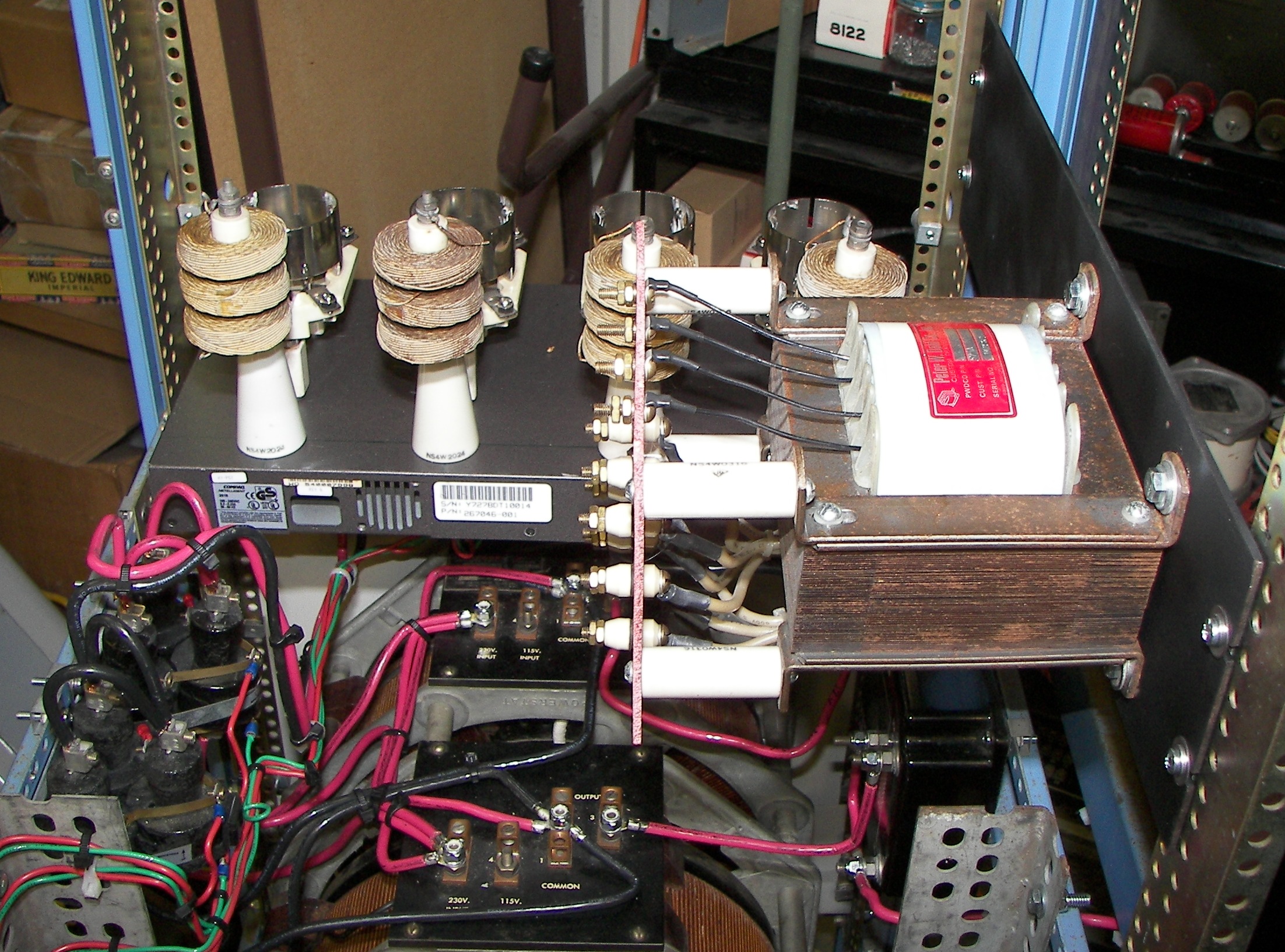
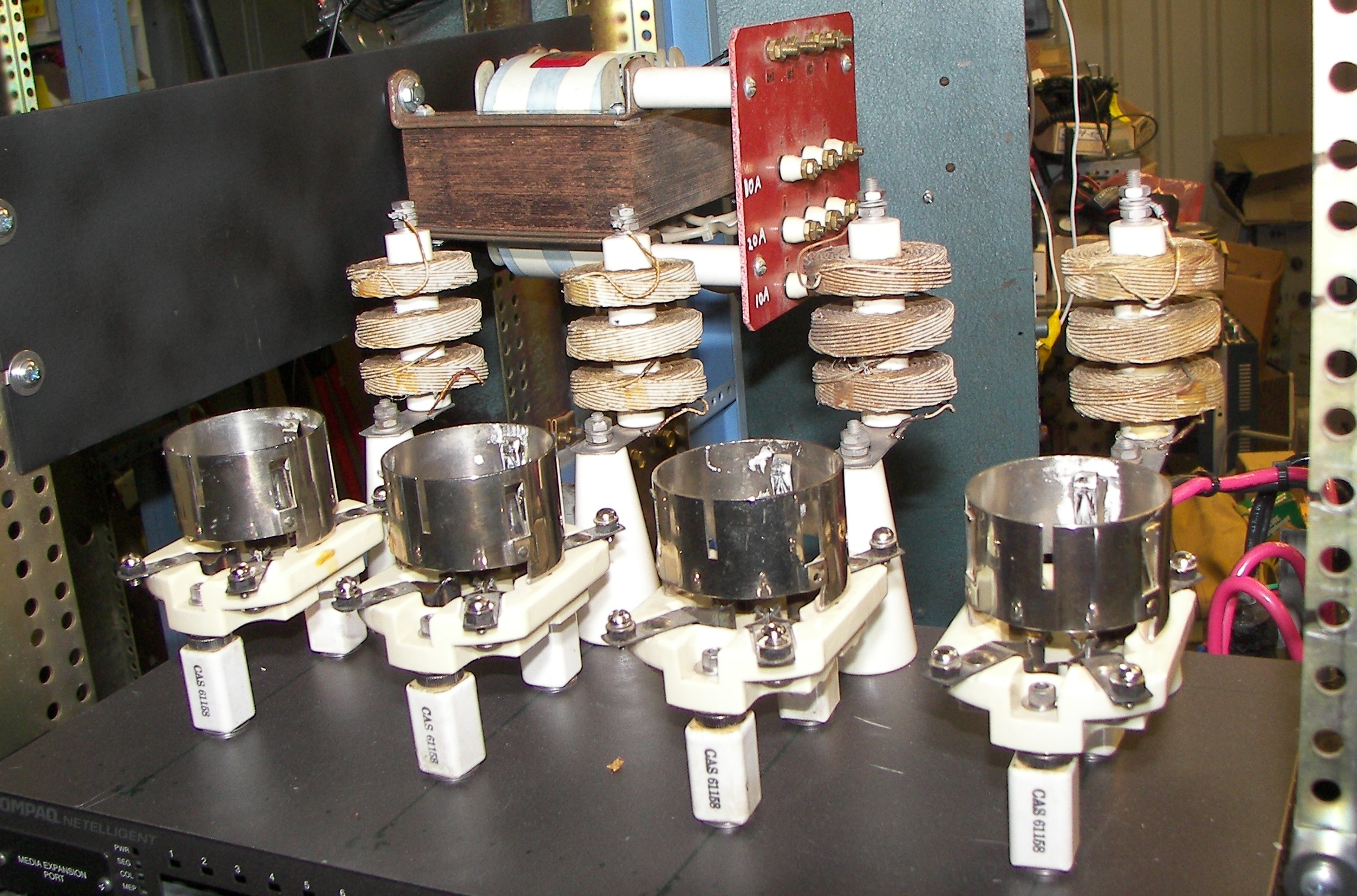
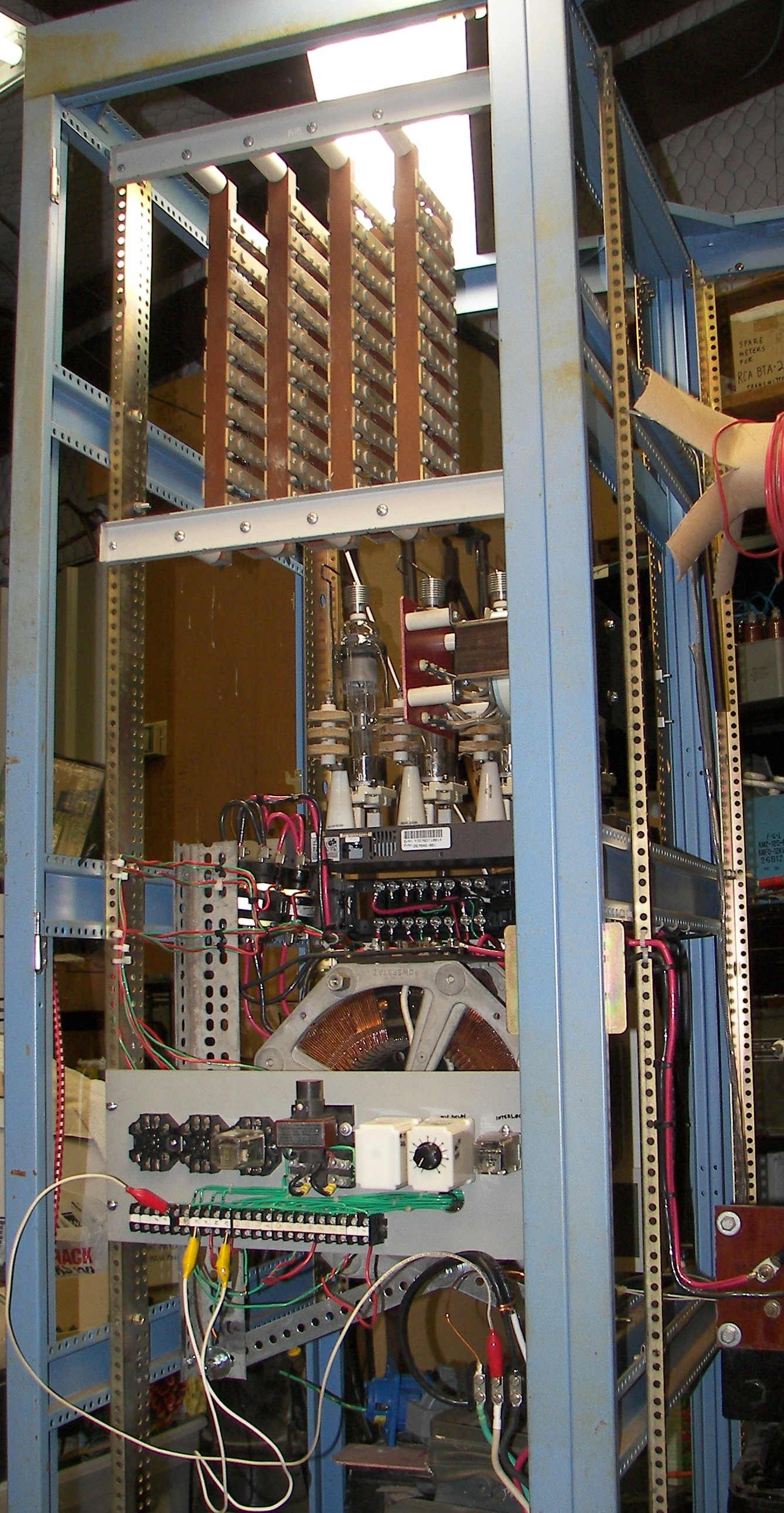
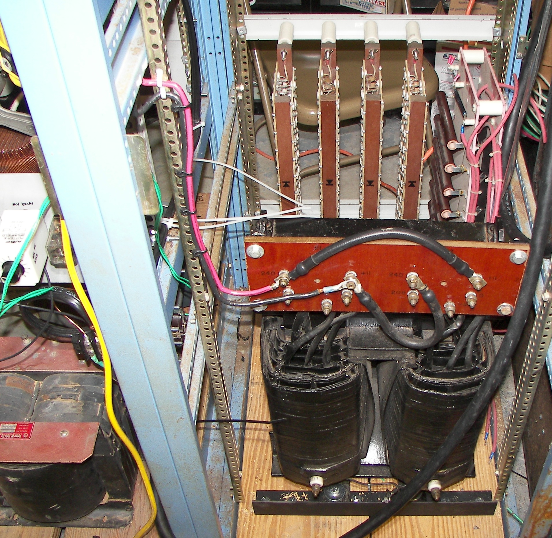
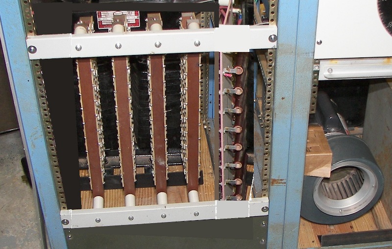
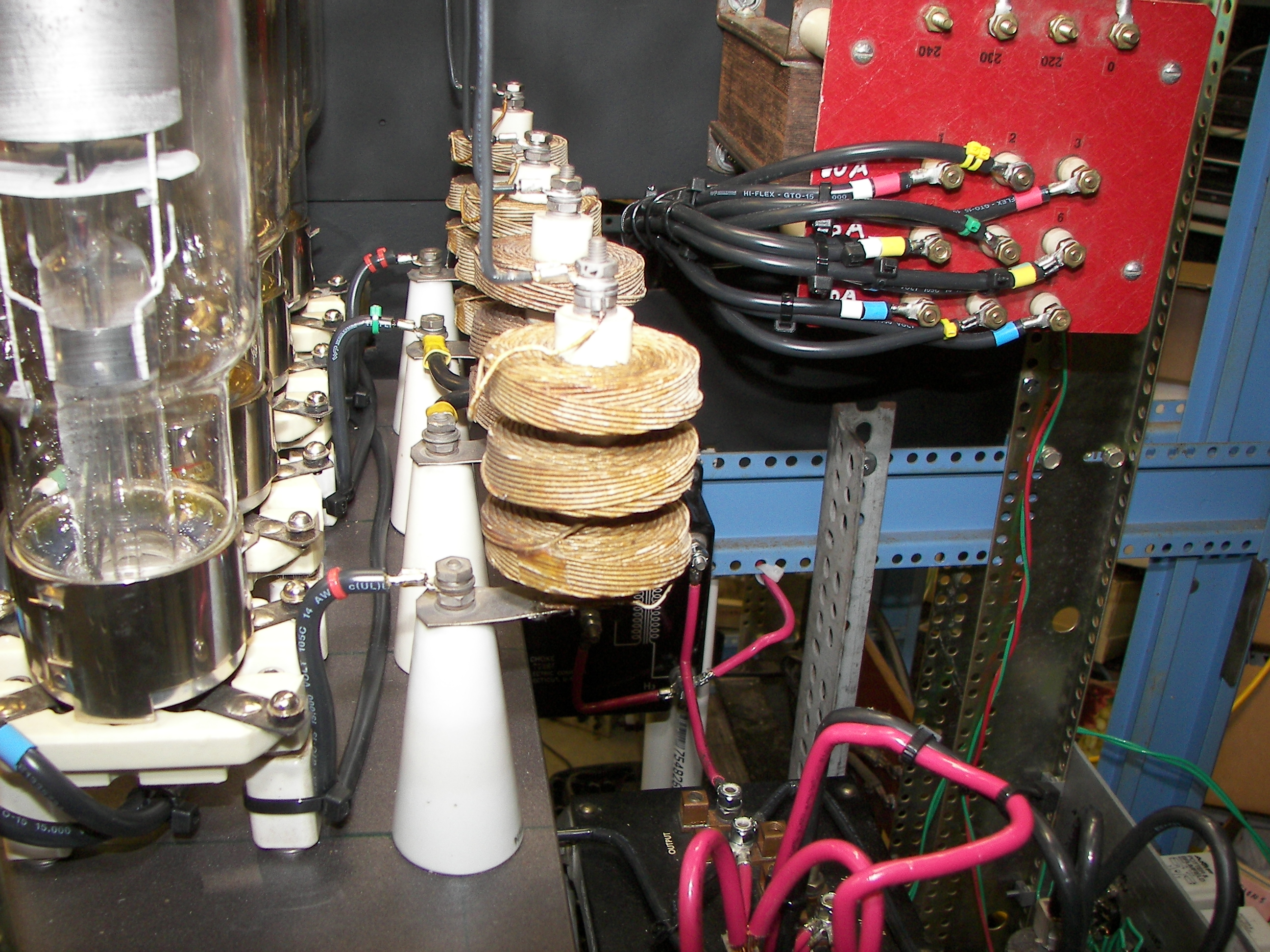
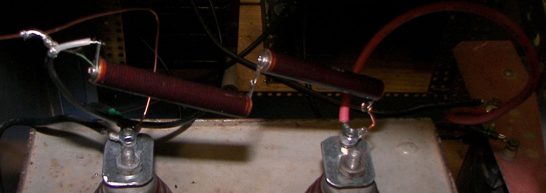
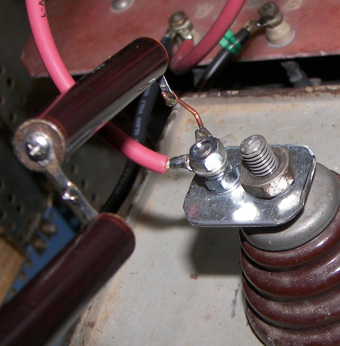
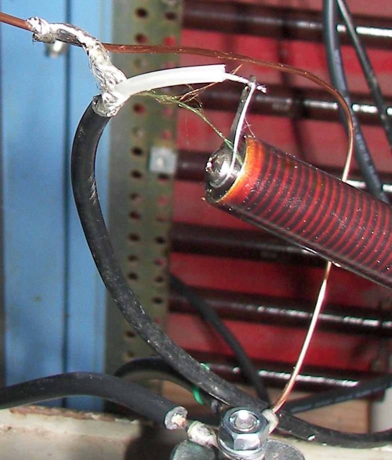
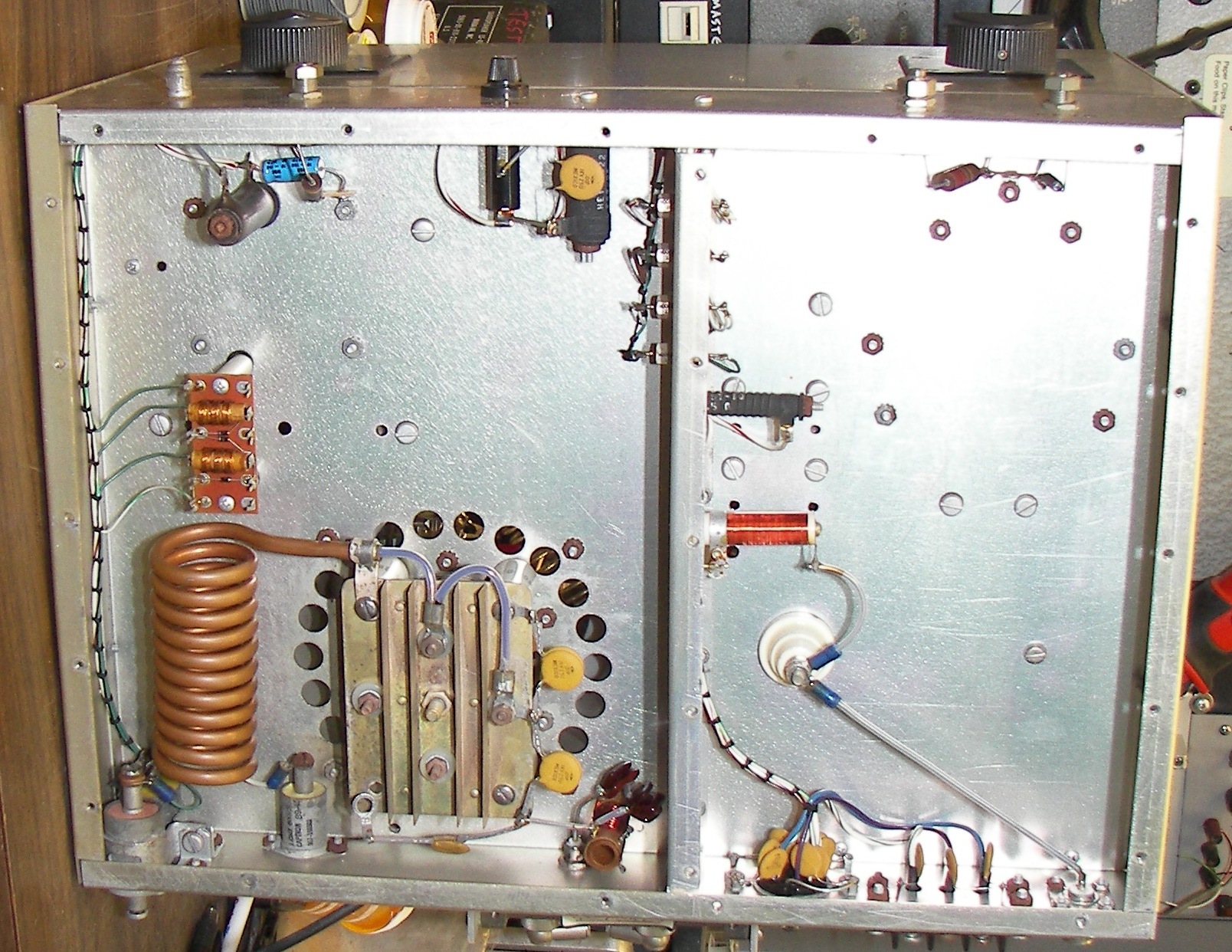
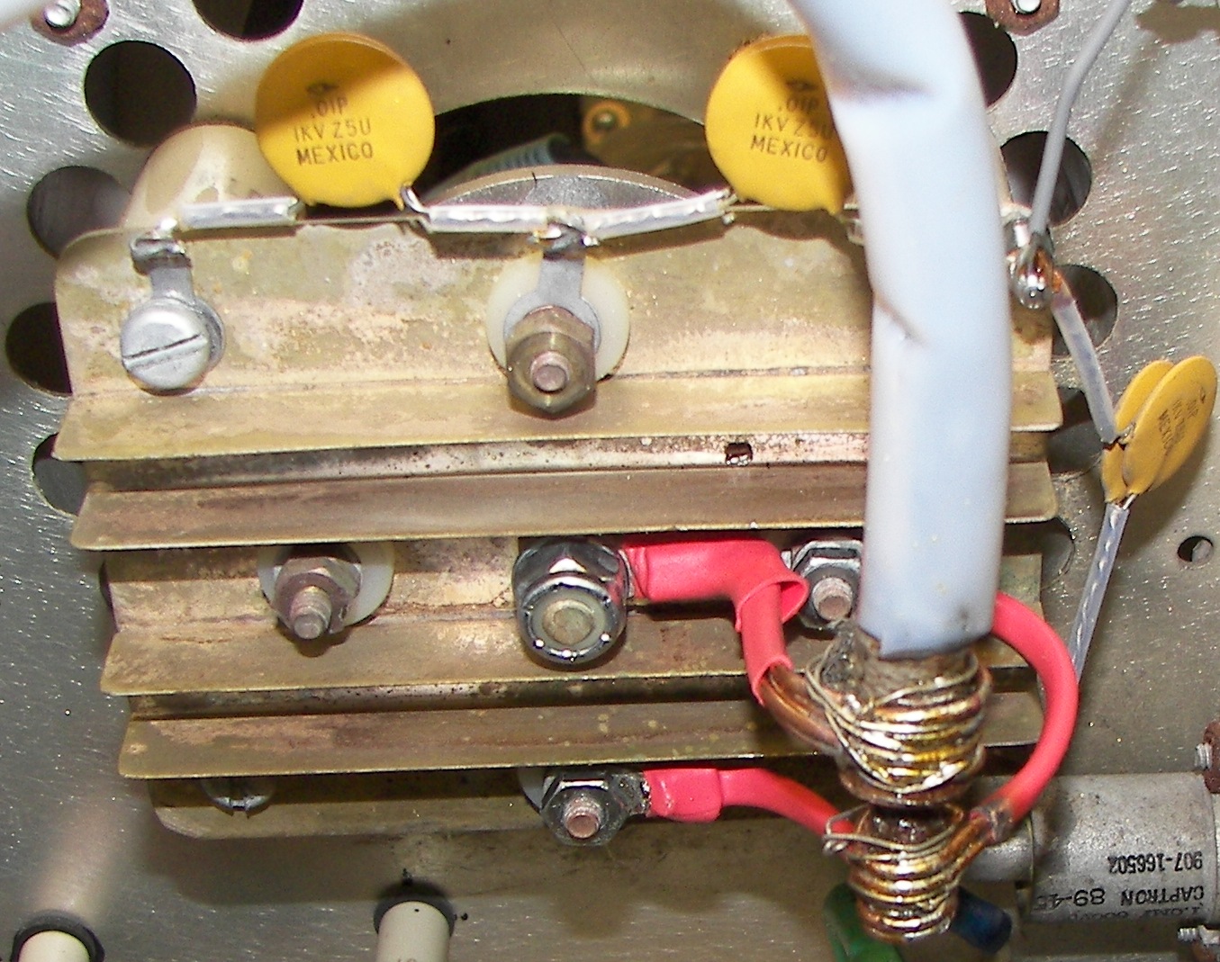
Each diode stack has 40 pcs. 400V/25A rectifiers. The PIV of the stack is 16KV. |
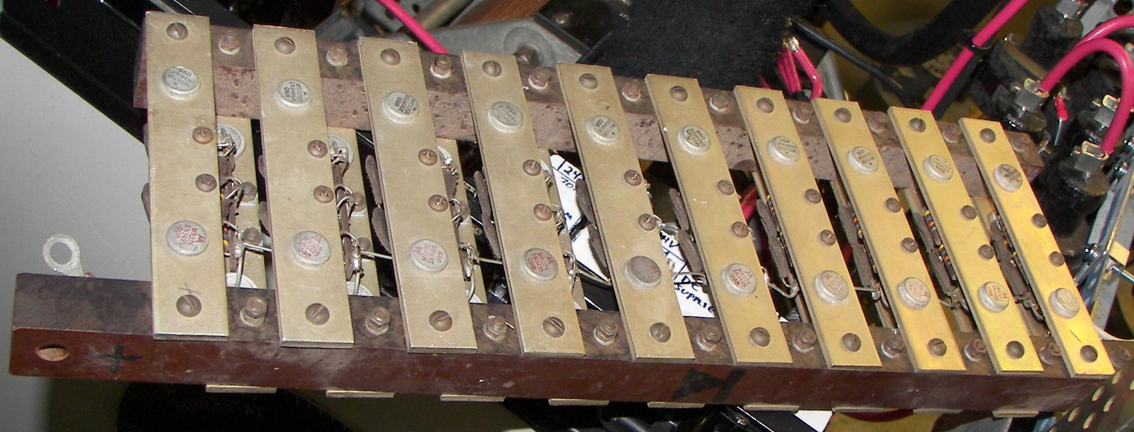
4 stacks will be used. One will be put in series with each Mercury vapor rectifier so that the PIV of any rectifier leg is 31KV. It may seem overkill, but the peak voltage across the rectifiers is close to 8KV under full voltage conditions, which is about half the rating of either the tube or the diode stack alone. The extra headroom and peace of mind is well worth the extra parts, which were just lying around anyway. |
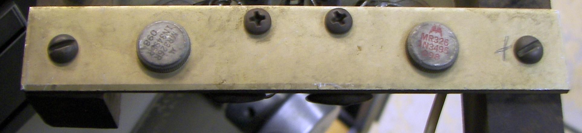
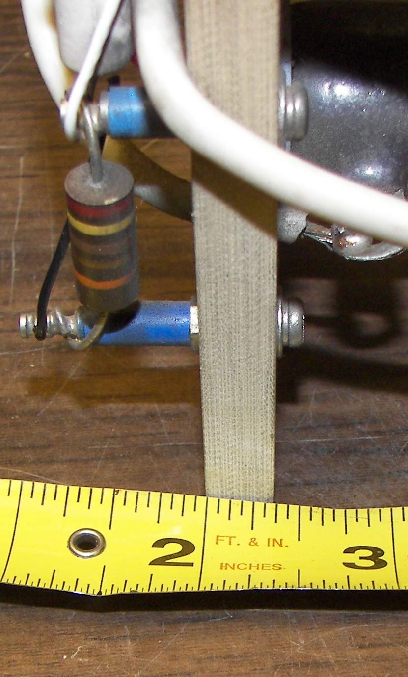
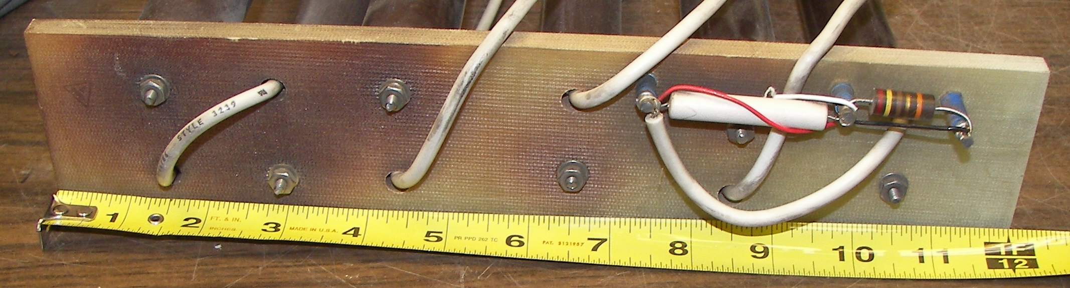
Each diode has a 47K/2W resistor and a 0.011uF/1KV capacitor across it. |
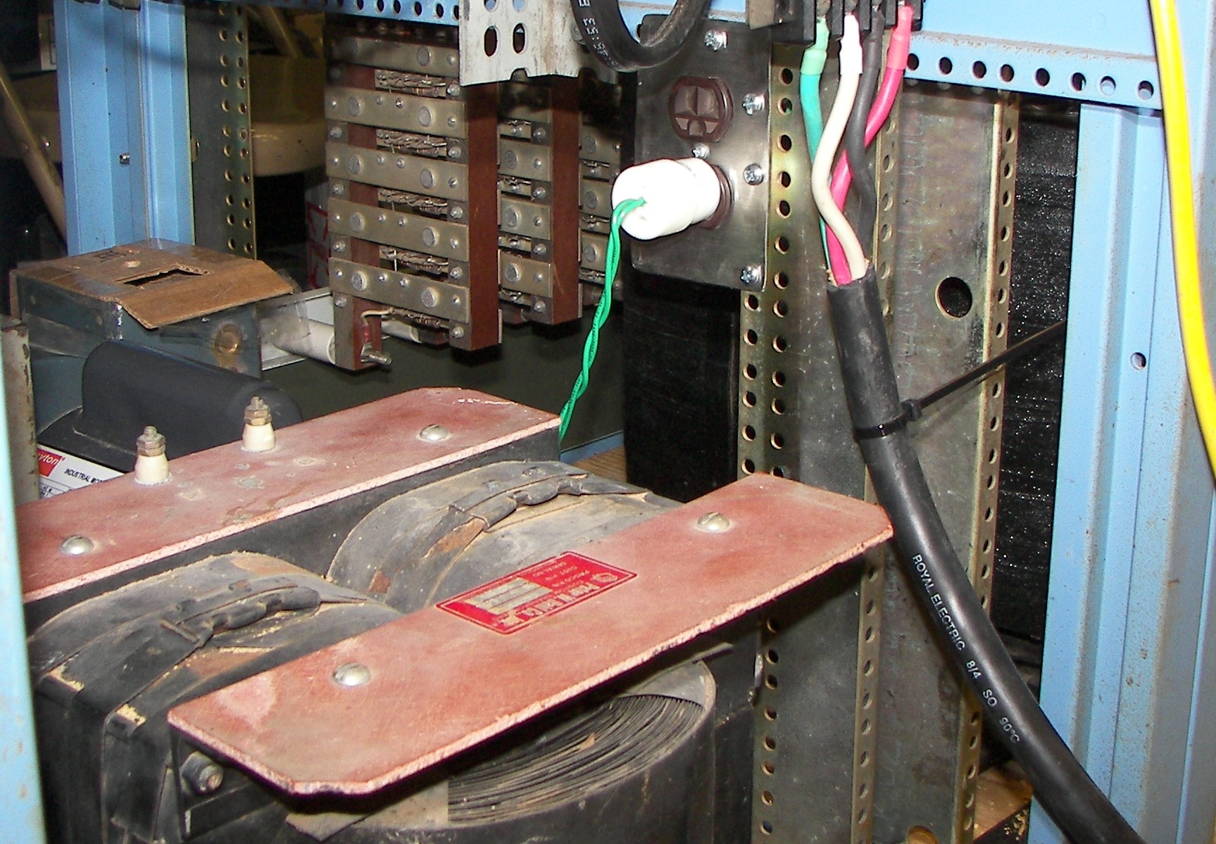
The business end of the HV transformer. There are two secondary windings and both ends of each are extremely well insulated from ground. These are put in series and the 'center tap', which is not used, is there in the middle, the two wires connected by ring terminals and a bolt. A lockwasher was used to keep this tight. It may be as well later to install a ceramic insulator to hold it in place. |
|
 A check of primary magnetizing current was performed. It's 1.6A, normal for something this size.
|

Temporary power cable - maybe overdoing it to cover the soldered rung terminals with color colded heat shrink, but it is going to be used for a long while until the amp is complete at which point a power connector should be mounted in the rear of the enclosure. |
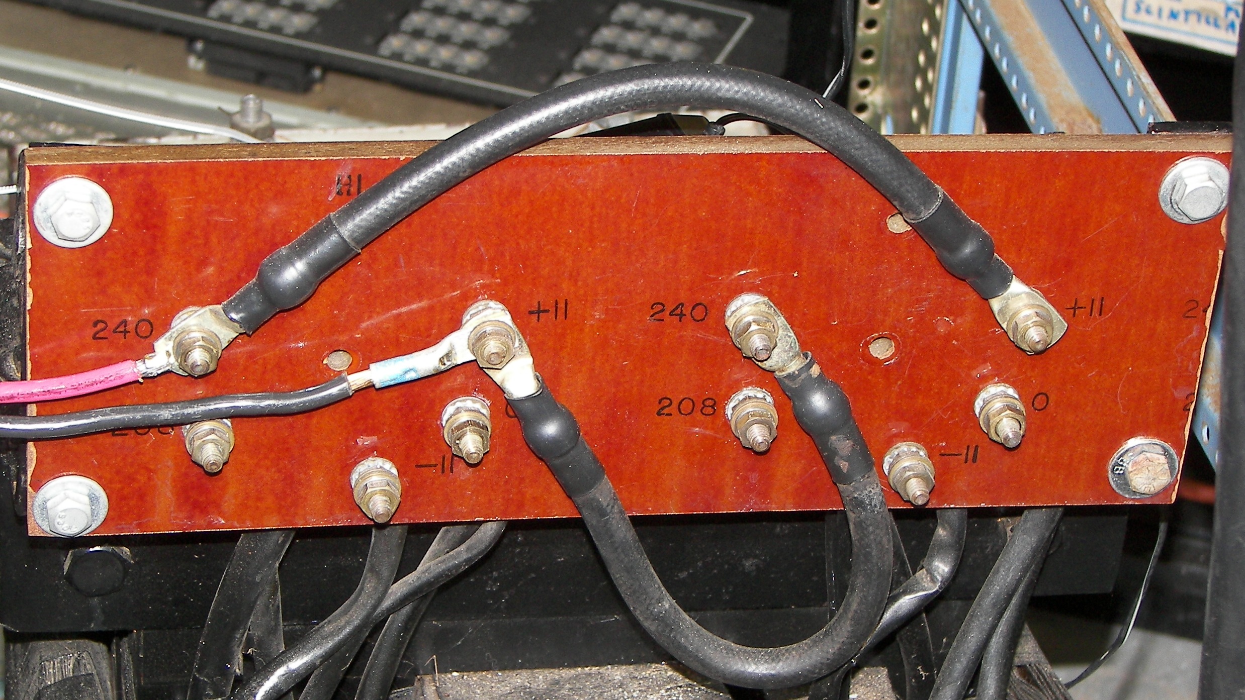
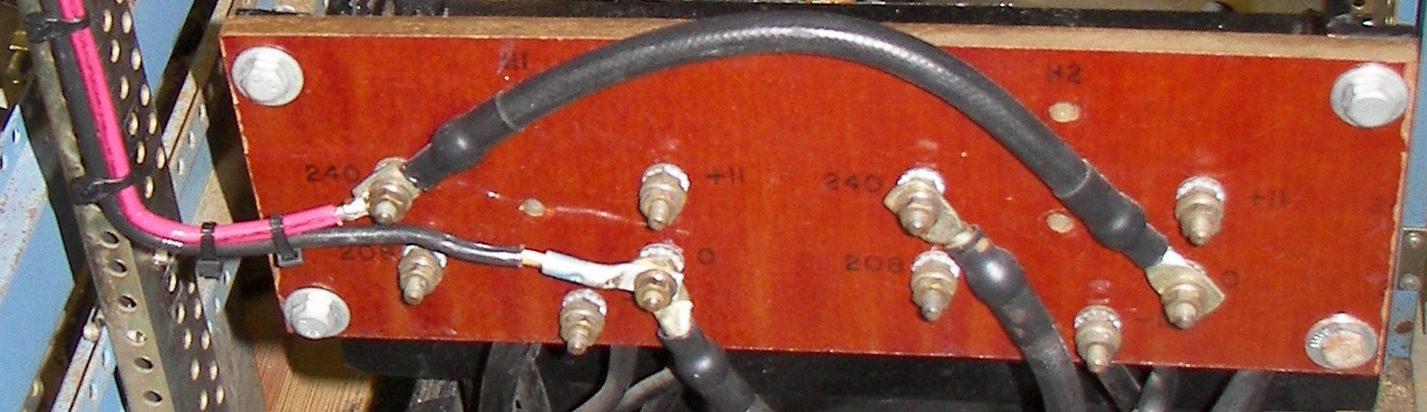
Taps changed to +11, one of several options for adjusting the maximum voltage of the power supply. Note the polarity/phase of the primary winding. In its previous career, the transformer was 3-phase, and all three secondaries were wired with the same phase since the three applied primary voltages provided the phase difference in order to make the the secondary voltages add. Now, the transformer runs from a single phase 240V line, so in order to add up the secondary voltages (5820VAC) rather than subtract them (0VAC), one primary has its phase inverted. If it had been fed the same way as previous, the voltage between the HV terminals would have been zero. The schematic diagram should help explain this if it is not clear. |
|
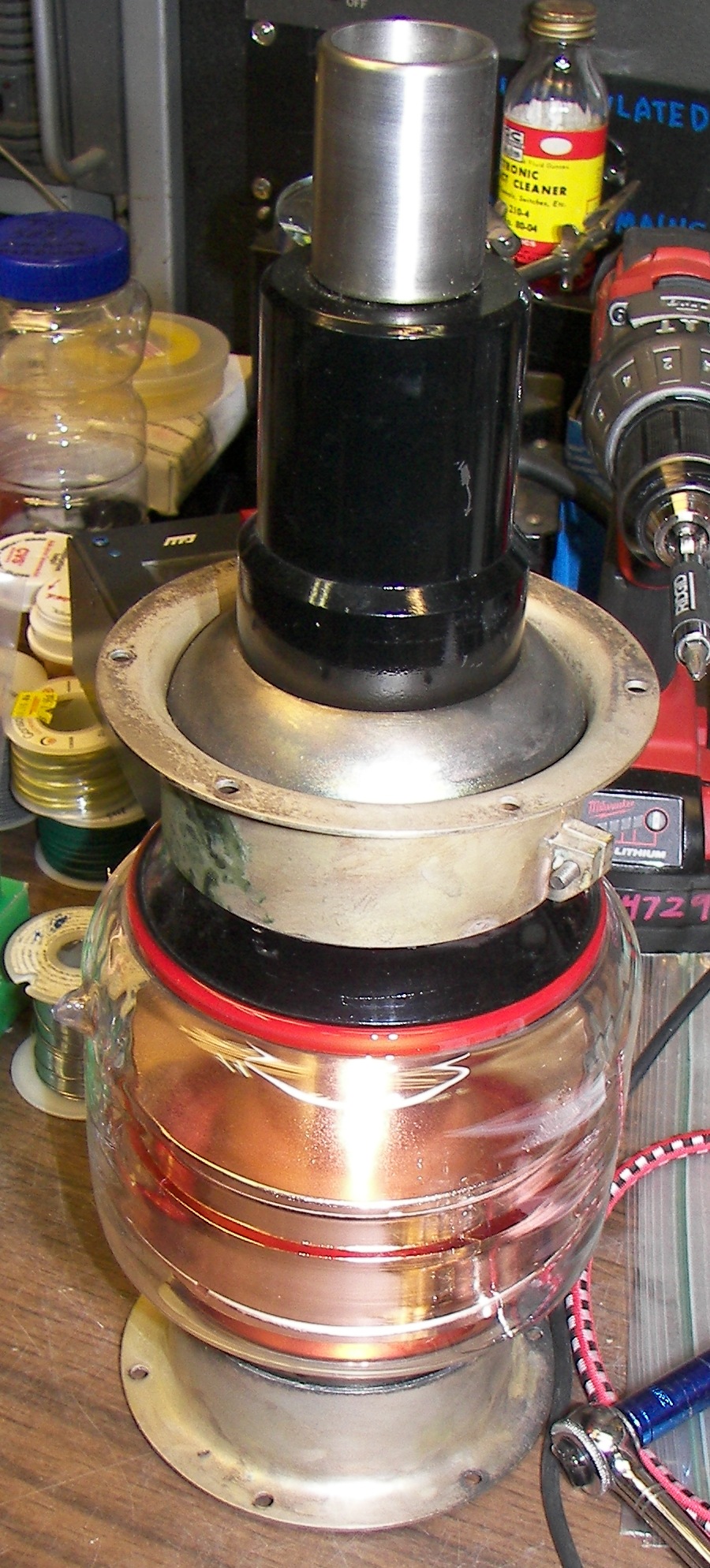
The Peter Dahl filament transformer was specially designed for a bridge rectifier of four 575A tubes. These rectifiers use 5V at 10A each, same as the 673s used here. It was not marked as to which winding was 20A and which were 10A so it was closely examined. Not surprisingly, all of them have extremely generous wire gauge. |
|
|
|
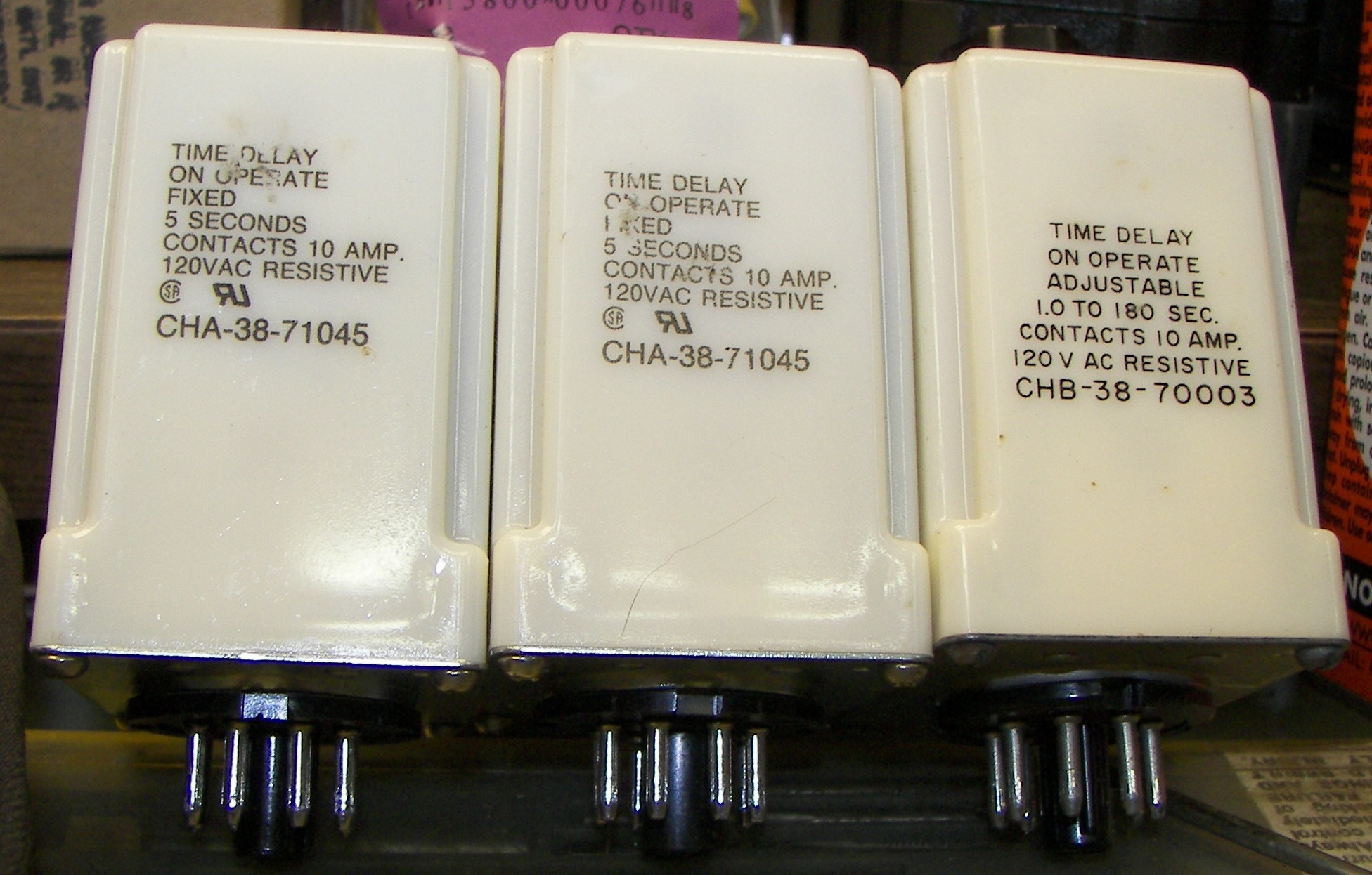
These time delay relays were used to sequence the amplifier startup and are electrically interlocked so that it will properly recover from any power outage or incorrect power switch operation. |

The fixed time relays are for plate and filament inrush control. The variable time relay is for setting the time for warmup on the mercury vapor rectifiers. Normally, 30 seconds is enough, but I prefer 60 to be on the safe side. If the amp has been moved around or if the tubes have been out of the sockets then the full 180 seconds is a good idea. The first time the tubes were tried, I let them cook for 10 minutes because they had been shipped and mercury was scattered throughout the inside of the device. |

Soft-start/Inrush time delay of 5 seconds was OK for first testing, but not practical in everyday use. Potter & Brumfield / AMF states that the timing can not be changed on their fixedrelays. This would be true for casual users, but the time is controlled by a small capacitor and it can be changed to adjust tie time delay. The original capacitor is a very good quality component not much affected by age or temperature, It is critical that the same quality of capacitor be used for the modification. In the experiment shown, a mica capacitor was used, but in practive, one will be used that fits properly into the case. A 1 second delay is good for filament inrush. For the plate, 0.5 seconds should be fine. |
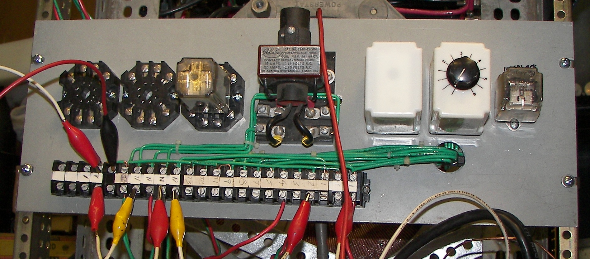
 At first, the small steel panel, a 'mending plate', was envisioned for relay mounting, but considering all the needed wiring and a terminal strip, it would have been much too small.
|

Nice chassis punch set is perfect for tube/relay sockets. This Japanese set is at least 50 years old and of good quality. It is somewhat worn but plenty of oil makes it go easily. |
An aluminum rack panel was used for mounting all of the relays. With the ever-growing number of terminals to connect, it's barely large enough as shown later. |
|
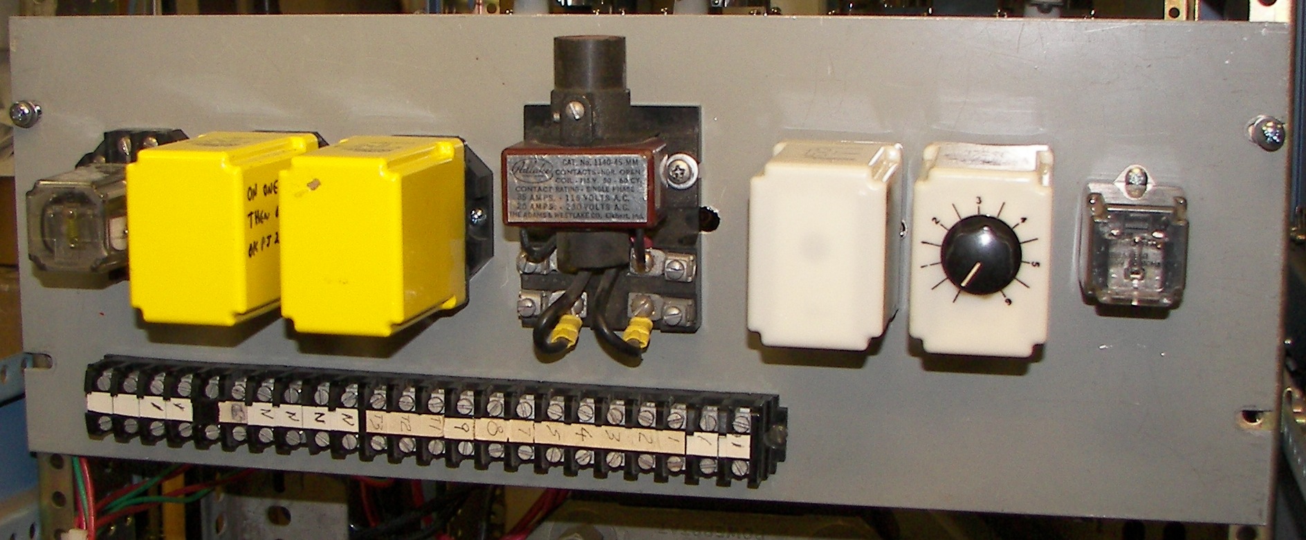
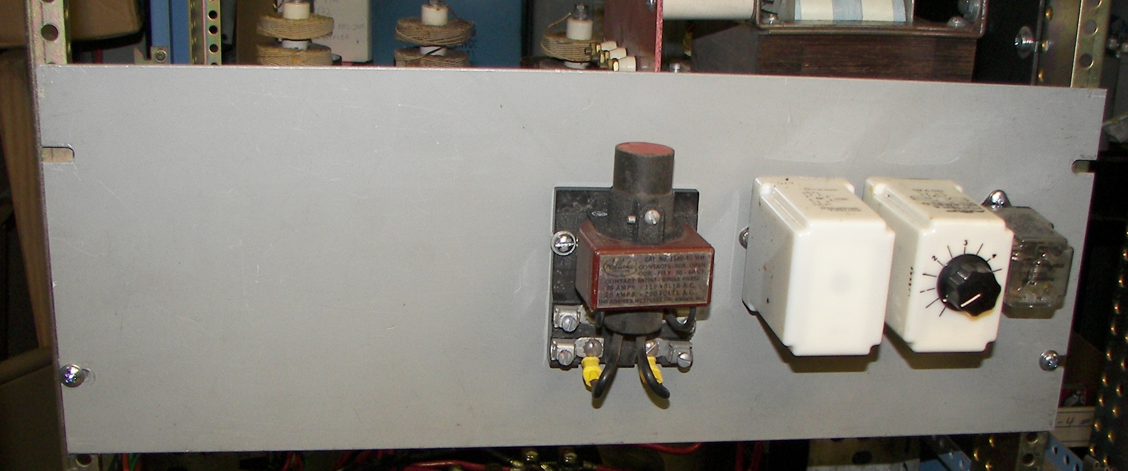
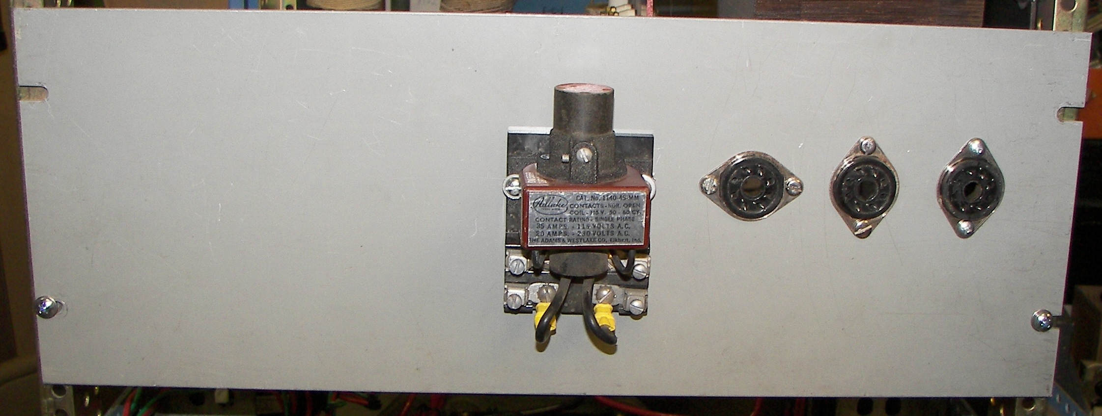
From left to right: 1. TBD possibly bias keying for standby/operate on voice modes 2. TBD possibly not a relay but a circuit board for QSK control, if it is practical on this amplifier (PIN diodes and fast relays cost big $) 3. Filament soft-start (all filaments but mainly to benefit the 3CX3000). 4. Filament contactor (all filaments) activated by air switch. Mercury plunger type. 5. Plate soft-start time delay. 6. Rectifier filament warmup time delay. 7. Interlock relay -If filament power has been interrupted for any reason, it enforces rectifier filament warmup time before HV can be reapplied. |

rear view of panel. |
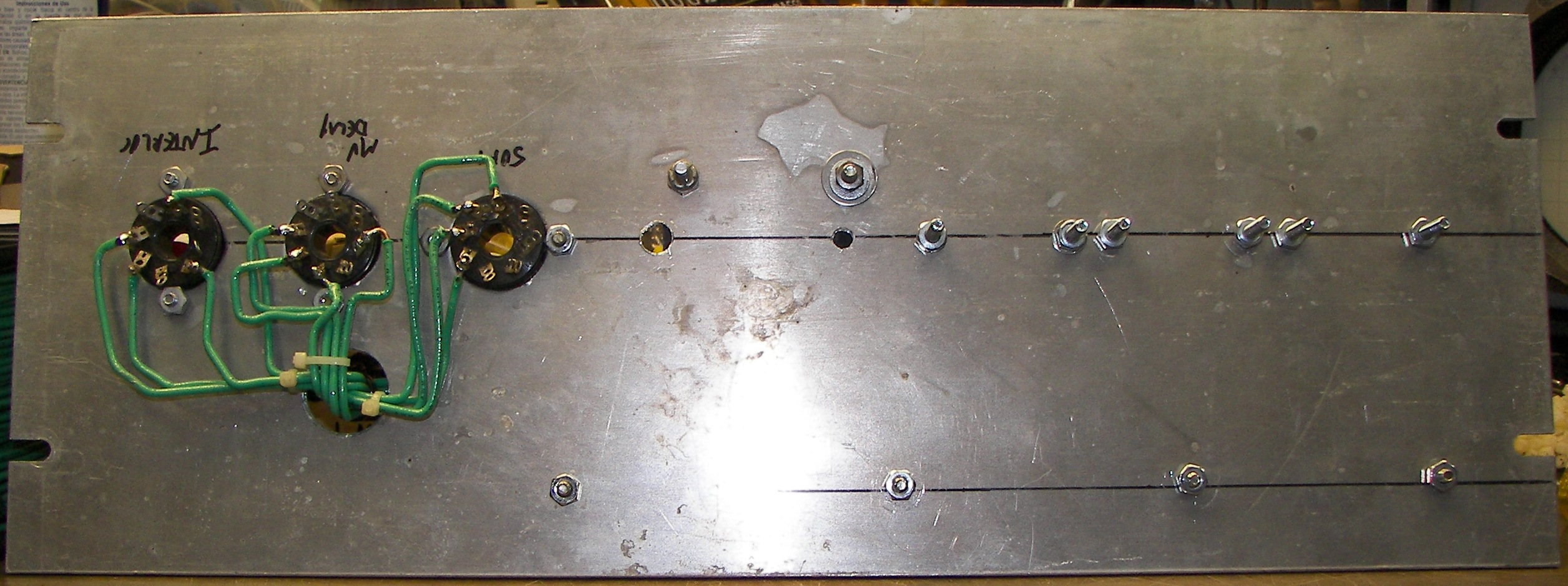
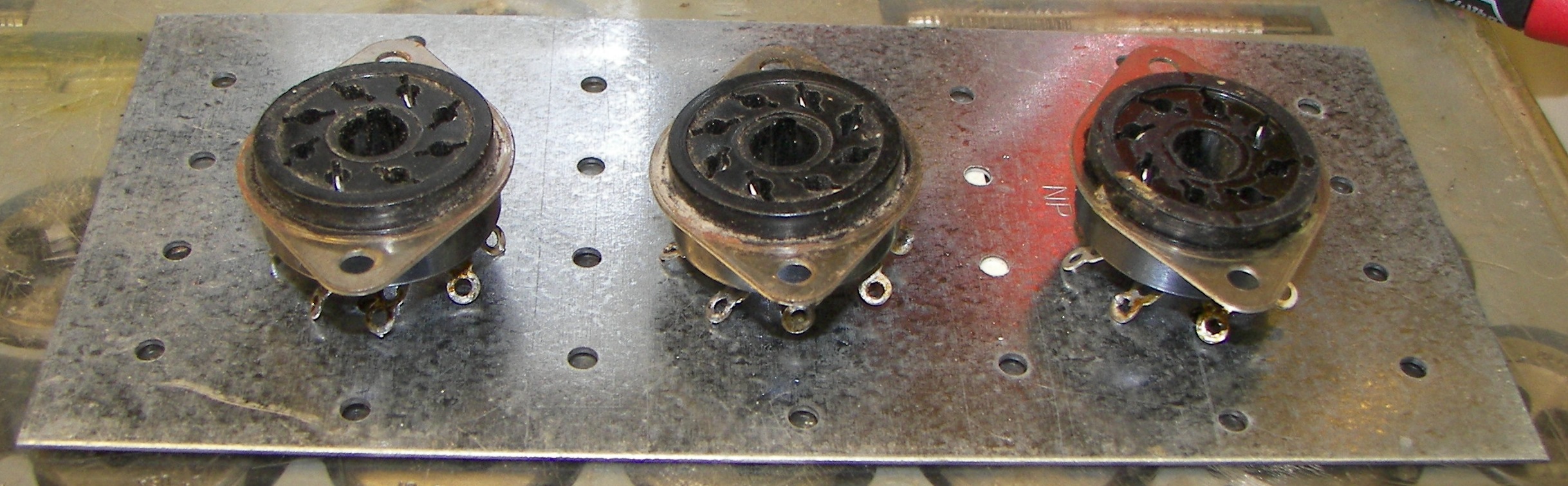
Many things change somewhat during a 'junkbok' project where components are found or traded. One proof of that is the three 'surface mounted' relay sockets. These are preferred because no additional hole is needed for wiring to pass through the panel to the terminal blocks. |
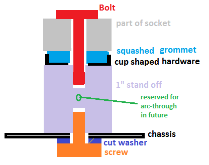
No grommet is needed since the stiff wires don't tough the edges of the hole but a piece of rubber tubing was later cut lengthwise and slipped in over the hole edge for safety reasons. |
|

|
one page of many notes in the process. |

|
Testing.. |

Testing.. In this case cheating the air switch to avoid the blower blast and noise while working on the high voltage supply. Listening for strange noises during HV supply testimg.. hums, sizzling, etc. bad things can happen when bringing 30-60 year old components up anew. |
|
Mercury vapor or gas rectifier hookups: When two gas rectifier tubes have their filaments connected to the same filament supply, the filament shield or anode return side of the filaments must go to the same filament supply terminal. Note that some old-design or low-power rectifiers of these types do not have the shield feature. It is still wise to connect like pins together in these types. For gas rectifier tubes in parallel, it is necessary to use an impedance in series with the anode. In the case of a resistor, it should create an average voltage drop of not less than 50 Volts. In case of an inductor, a value of 1/6 henry should be used for 50-60 cycle operation. Inductances are preferred because they minimize power losses and help to limit the peak anode currents. Center tapped inductors (interphase reactors) can be used as stabilizing elements for pairs of parallel tubes. These inductors assure simultaneous starting and equal division of current. For gas rectifier tubes with anodes in parallel, corresponding filament terminals must be connected together. Failure to do this will cause unbalanced voltage drops in the tubes and make it necessary to use undesirably high stabilizing impedances. When two gas rectifiers are used without a center tapped filament transformer, the filament shield (anode return) pin must be used as the B+ output terminal. |
|

|
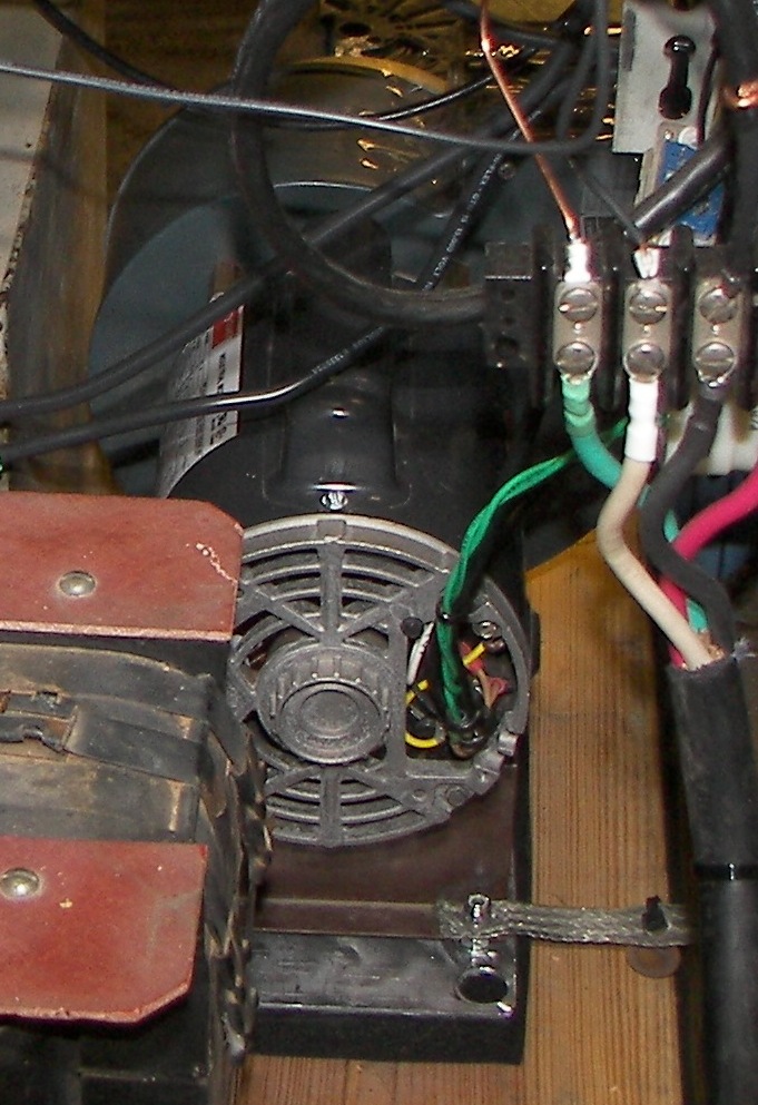
The rectifier filament transformer mounts to a steel rack panel. The black panel below that is painted composite. |
|
Filament: First Heat! The condensed vapor is very pretty. |
|
rectifier view from seated position. |
rectifier view from standing position. Just making sure the glow will be readily visible. |
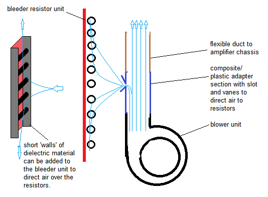
A way to cool the bleeders if desired. They are mounted on a red fiber-type phenolic board with about 1/2" spacing from the bodies to the board. In case the resistors become too warm it would be a shame to discolor the mounting board. The blower seems to have enough air, but that will be checked when the project is tested with the tube in-socket for anode temperature measurement with projected dissipation. |
|
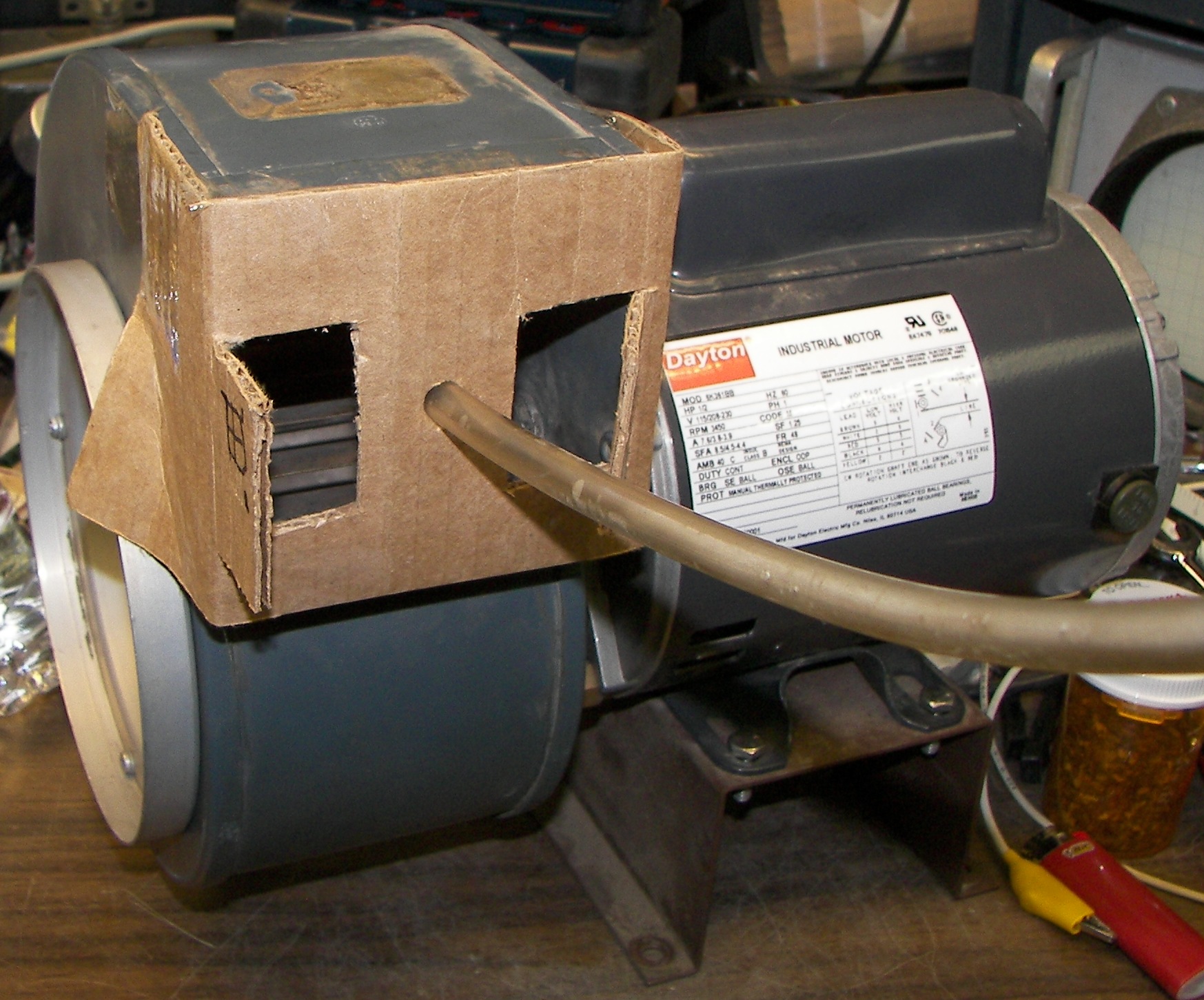
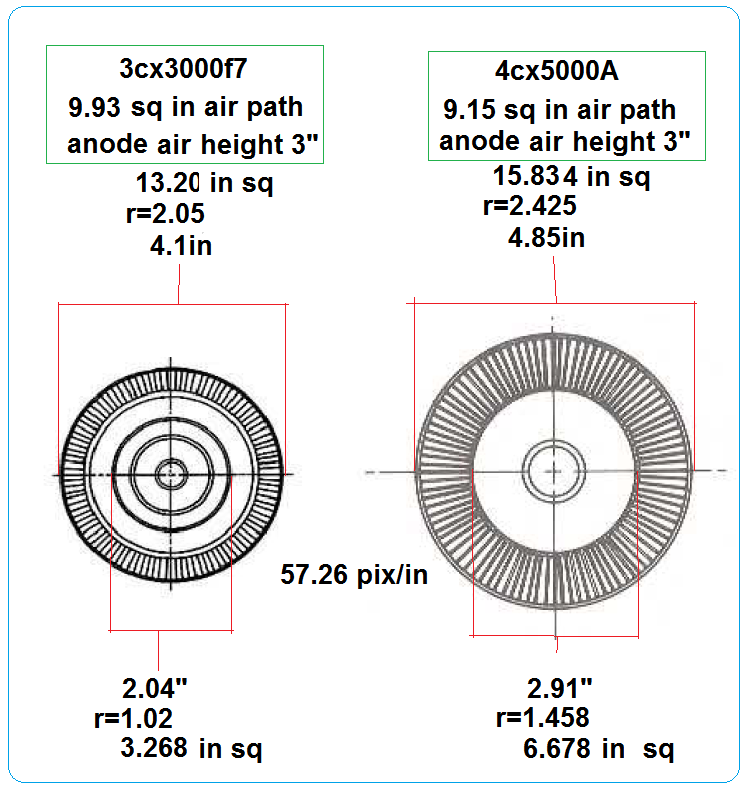
Blower testing for pressure. Looks like 2.25" with the bleed shown. The blower kept a pretty constant pressure over a wide range of airflow. Its current increased or decreased as the bleed door on the test fixture was varied. This blower is from a transmitter where it cooled a 4CX5000A and two 4-1000s. Interestingly, considering relative inner and outer anode diameters (the fin volume excluding the volume of the metal fins themselves), the 3CX3000 has 9.93 square inches and the 4CX5000 has 9.15 square inches. |

Blower off. 0" H2O. Because one end is connected to the blower and the other end is open, and the blowe draws air from the same pressure as the open end (atmospheric), the pressure differential in inches of water is equal to the difference in height of the water colum side to side. The height or size of the columns don't matter, as long as when the system is at rest the water columns are at equal level. For water, at least a 1/4" diameter column is good so that errors from cappilary action are minimized. |
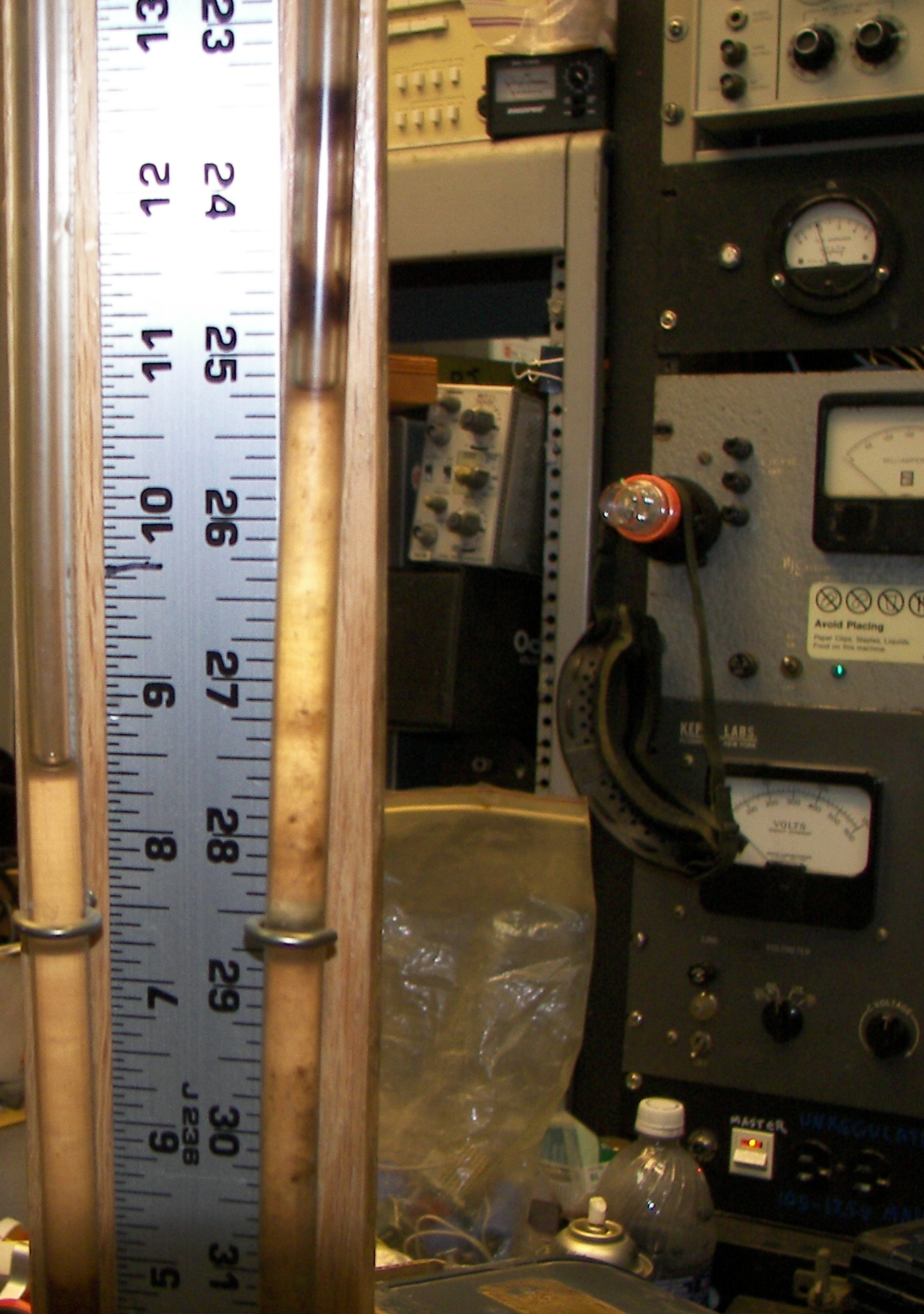
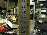
Blower on. 2.25" H2O - as indicated on a home-made water manometer. It can be made from a stick of wood for a base, a yard stick (or meter stick if you like), some clear flexible plastic tubing, and a few screw-in hooks (brass here) to hold the tubing against the wooden base. Time was taken to sand and varnish the base. Aside from some old stains from water being heft in too long, it looks pretty good for having been made 15 years ago for a class AB1 4CX5000A project. |
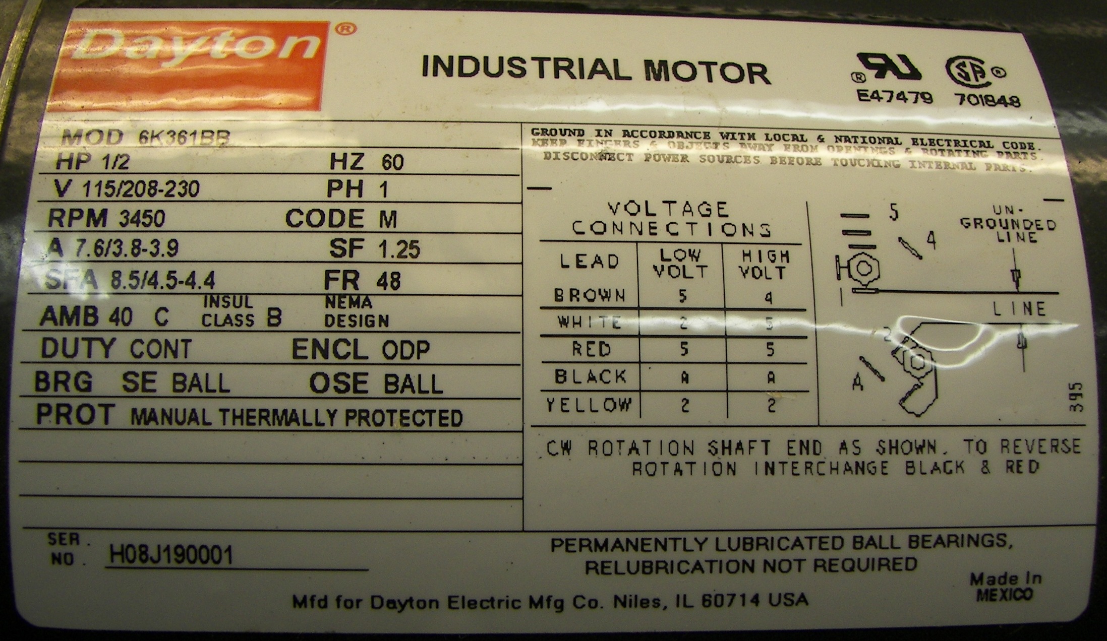
Nameplate for the chosen blower. 1/2HP, 3450RPM, 115/208/230V. Blowers of similar wheel size and blade type running at less than this speed (1750RPM for example) do not generally provide enough pressure for large external anode tubes although they work well for small tubes like the 4CX250B and most large glass tubes with or without chimneys providing that air path restrictions are avoided. It makes some noise but some sound deadening material can be put in the cabinet to reduce the dB. Whatever happened, The tube data sheet was observed when looking for a blower. The tube requires 1.4" H2O at the socket. The possible resistance to airflow in the as-yet unbuilt ductwork was taken into account when deciding on this blower. A much larger blower was available, but it was 3-phase and 1.5HP, 5450RPM. Yes 1000CFM @ 4"S.P H2O would have been wild, but was far too much and the motor would have overloaded with the low airflow permitted in this application. A costly 3-phase VFD would have had to be purchased as well, violating the 'junkbox' ethic of the project. It was run on capacitors for a test and sounded like a hurricane. It would have been almost impossible to muffle. |
Just a video of the blower and manometer in action. |
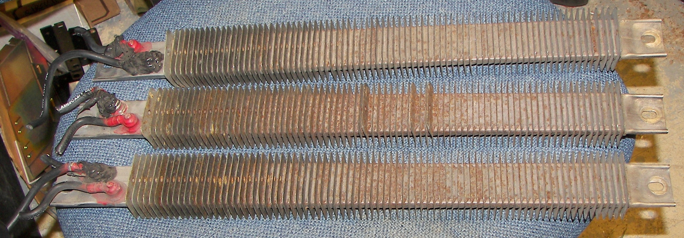
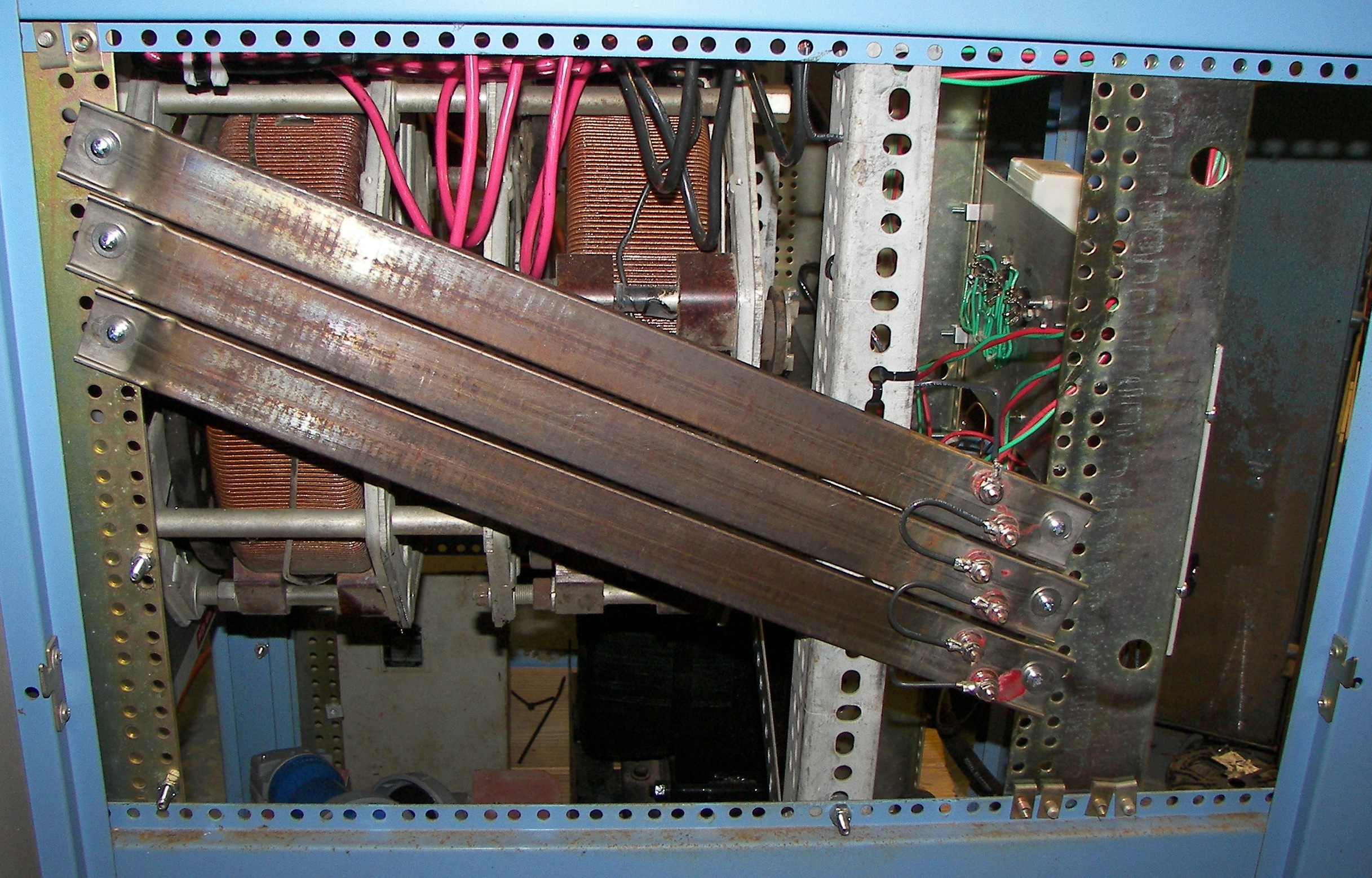
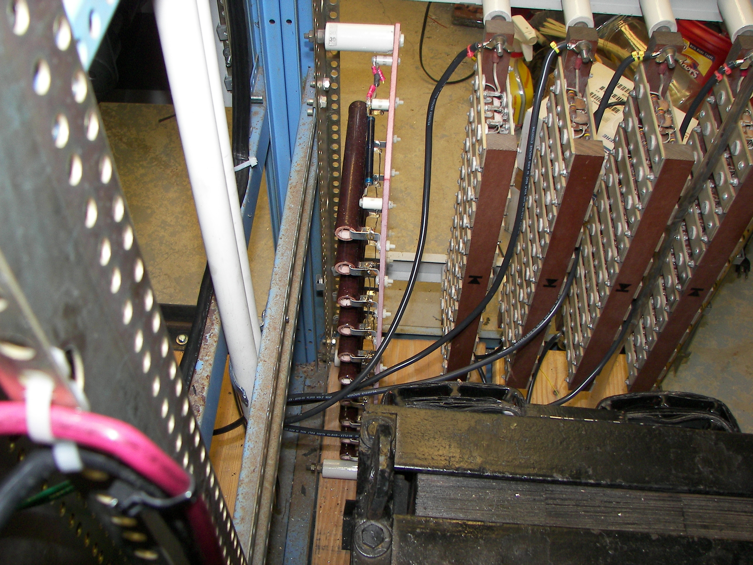
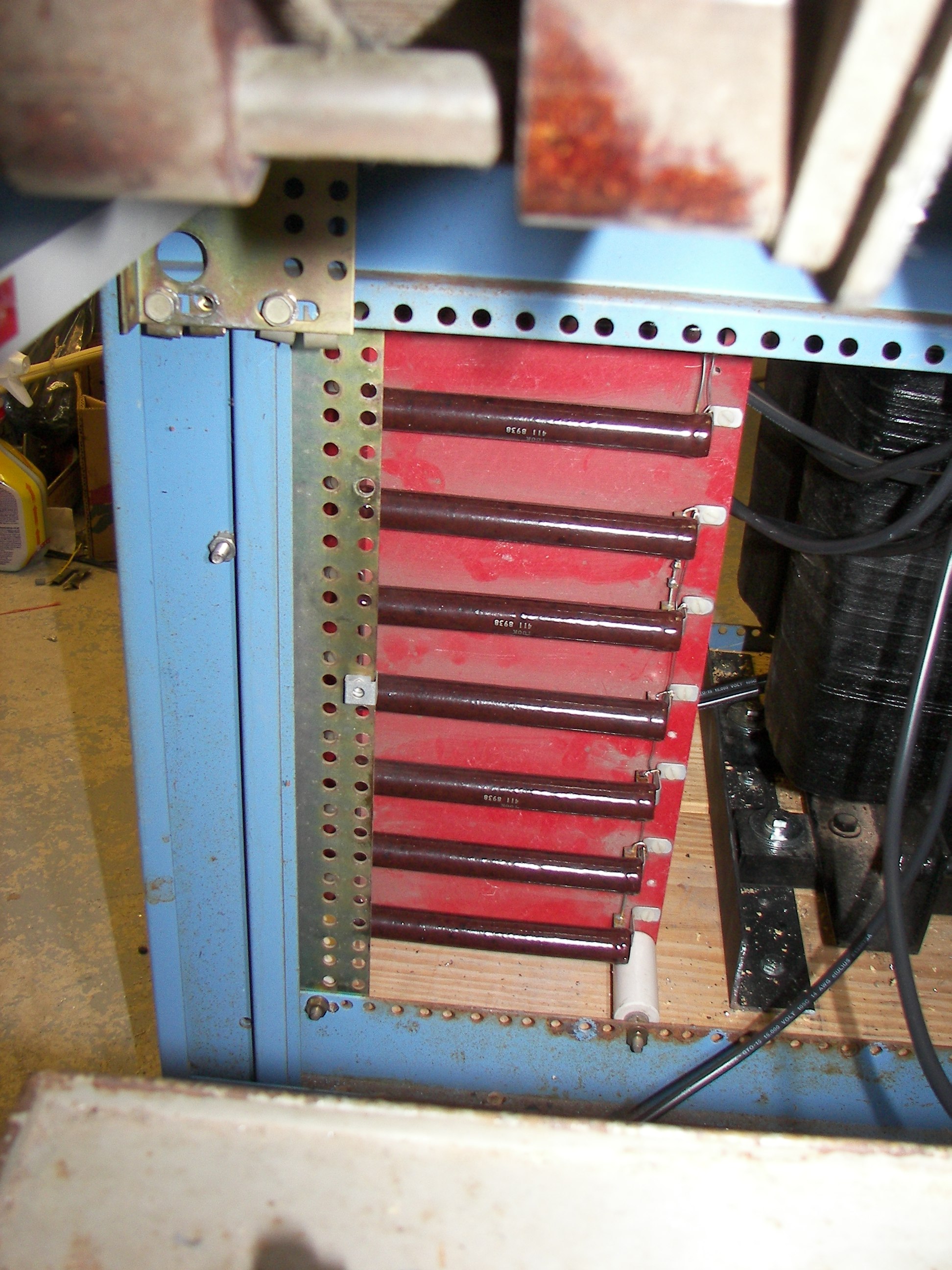
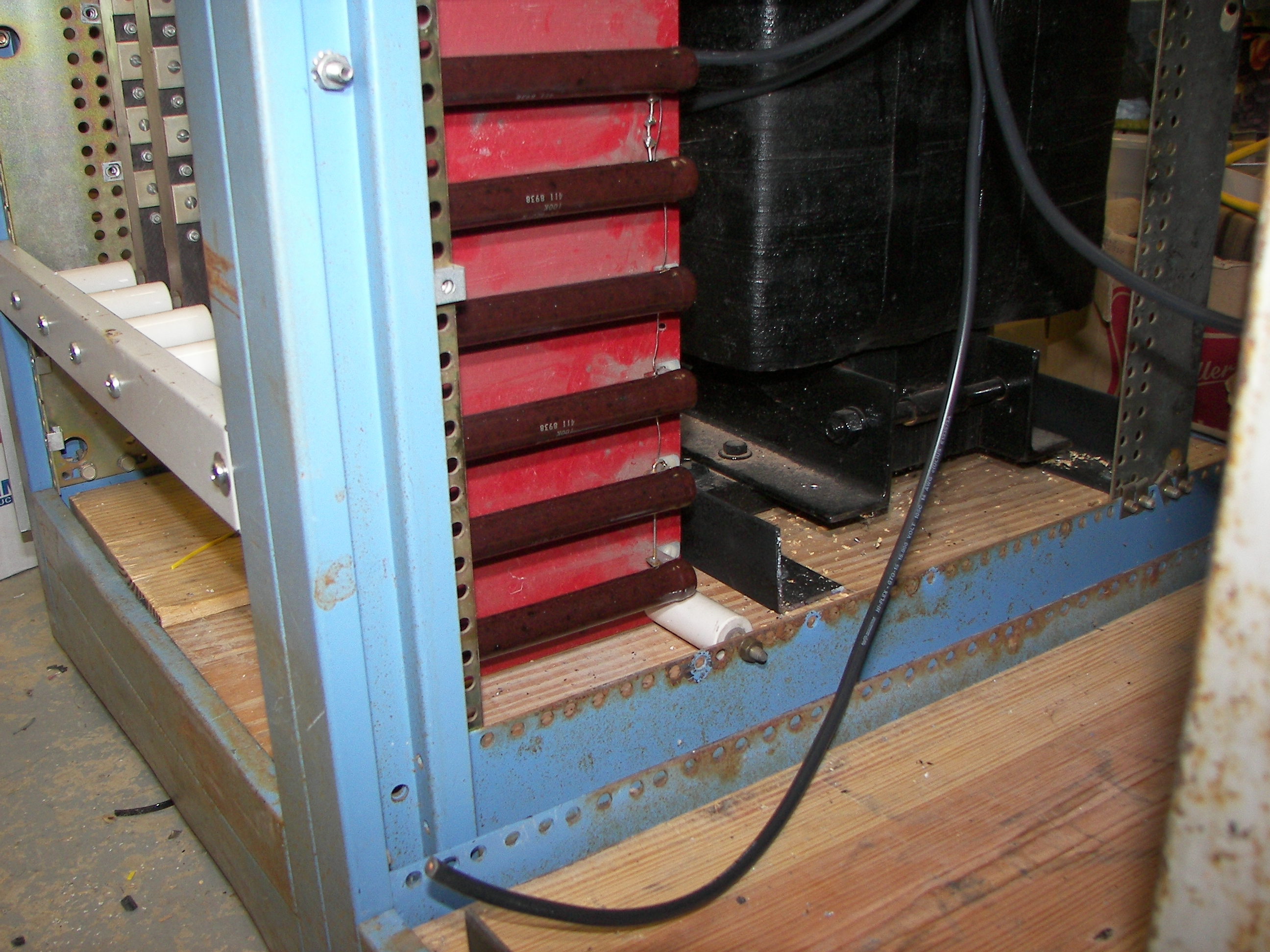
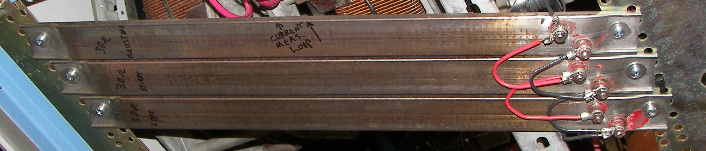
Plate Inrush resistance. These are industrial heaters. Each one measures 30 Ohms and is rated about 500W. Surplus from Murphy's Surplus in El Cajon, CA. These were very economical to obtain. Please visit these nice people if you get the chance! |

All this silicon coating had to be removed. It peeled off easily with side cutters. The fins also needed to be removed to make it easy to mount the resistances to the rack. They snapped apart at the corners and came off with a twist of a large pair of pliers. The manufacturer supplies these with fins optional, in case new ones are wanted. |
The many holes of a good rack make for a straightforward job. There is plenty of clearance between the terminals and the side door. A little 'Scotchbrite' took the loose surface rust off. |

|
|
Checking how the choke, filter cap, and blower will all fit on this side. Note that the blower outlet has been rotated to face up. |
Same for this side. |
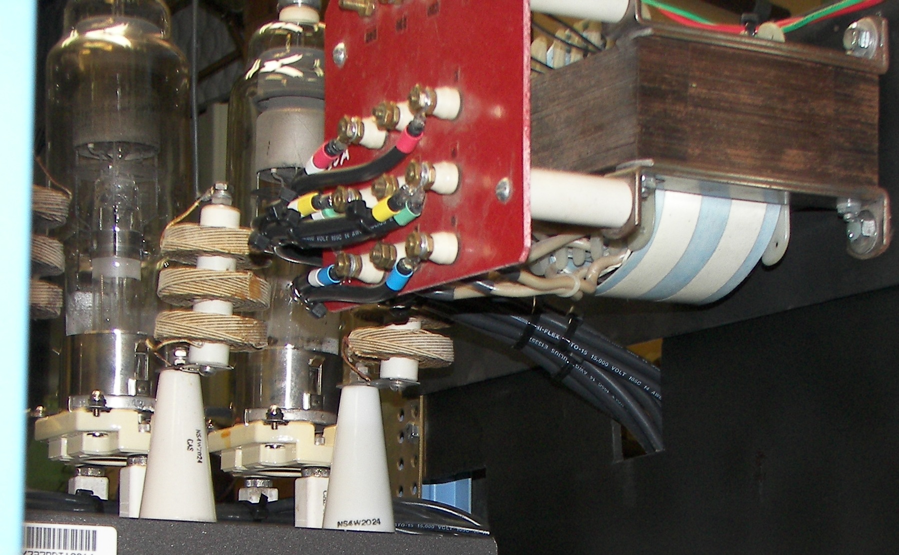
The bleeder resistor board has not yet been prepared. The rectifier board has to come off and the 9-resistor bank rewired. |
|
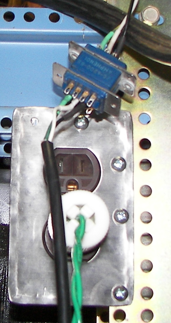
A 120V receptacle is installed for the blower. |

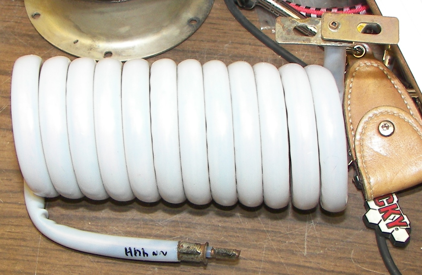
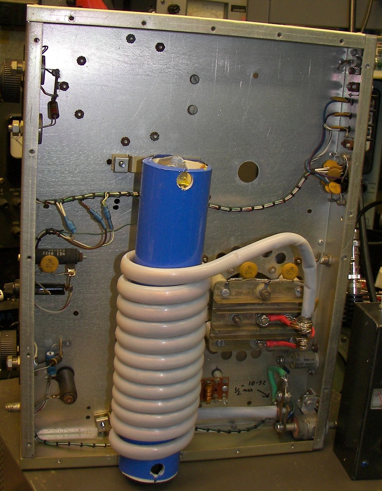
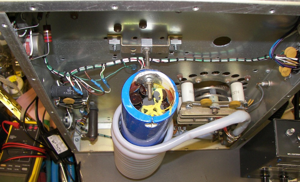
Some of that 15KV wire |
Simple PVC tubing keeps the HV wires safe and orderly. |
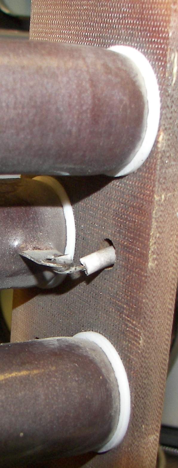
Wing nuts from the original rectifier diode installation make it easy to remove a stack for repair. The insulators are the same ones that supported the stacks originally. |
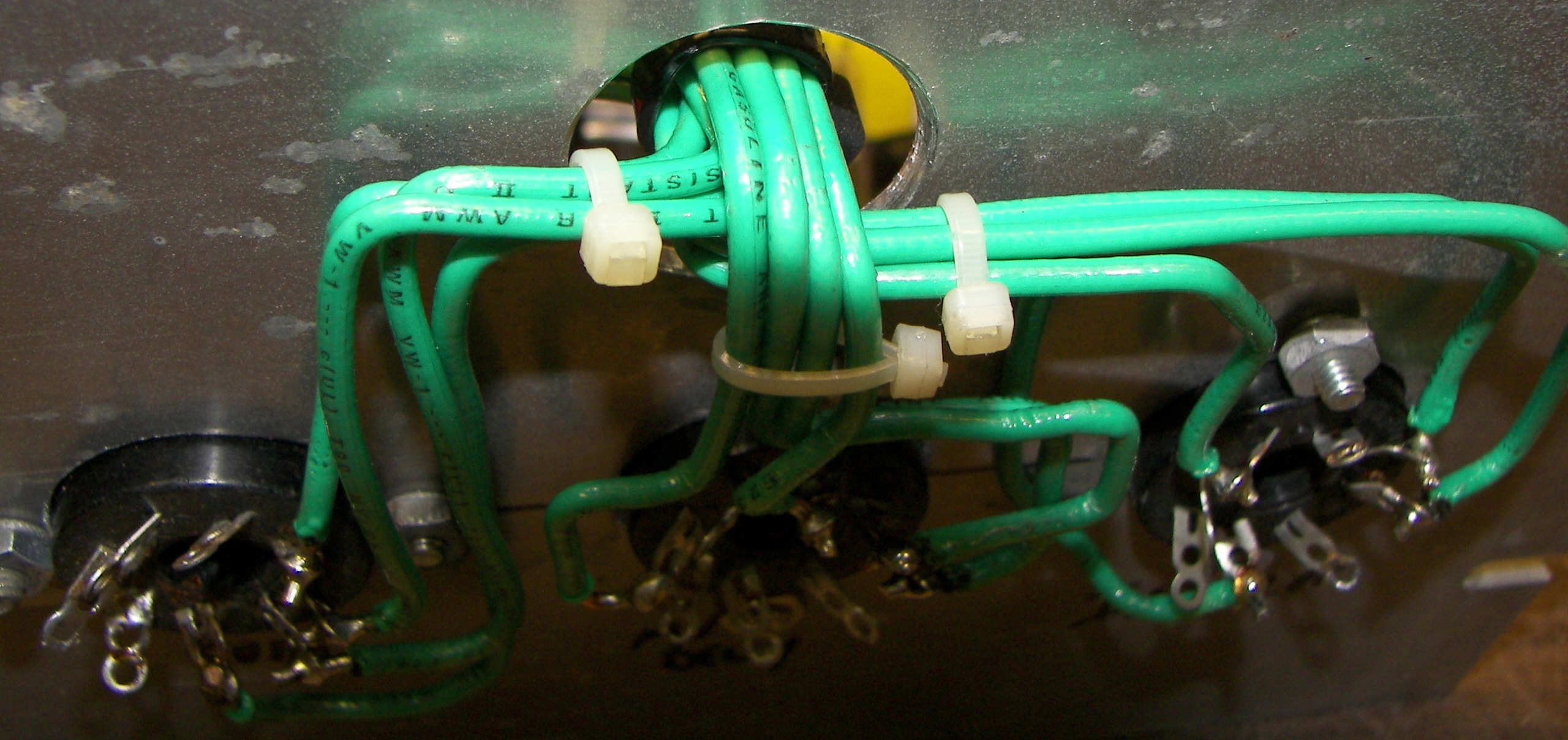
Color coding the HV wires for the filament transformer helps a lot for checking things later. |
The bleeder board is rigid and supported by insulators at three corners. |
In this location, the bleeders are next to the blower location. A small jet of air from the blower's outlet, if available or neccessary, can cool the resistors. |
|
This is what happens... |

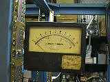
Temporary HV meter, 0-10KV. |
video of HV test. Nothing really to see.. running up from 0 to max. of 6200VDC and back. |
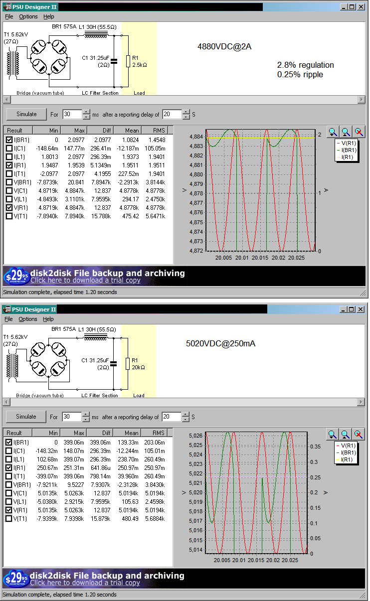 Power supply performance simulation. The results match pretty well for regulation and ripple. Free program from duncanamps.com
|
6400VDC max. on bleeder load. At some point the taps on the transformer can be changed to adjust the voltage lower. The costly tube is rated 5KV maximum. |
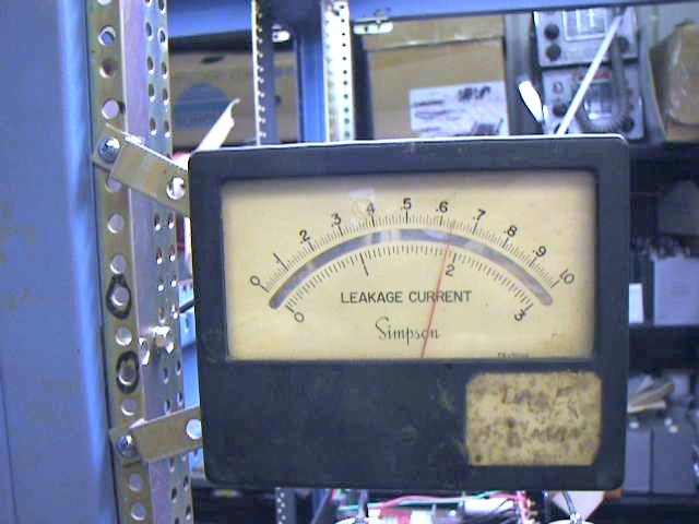
Temporary HV multiplier. Genuine HV resistors.. May or may not be used later depending on choice of meters. |
|
|
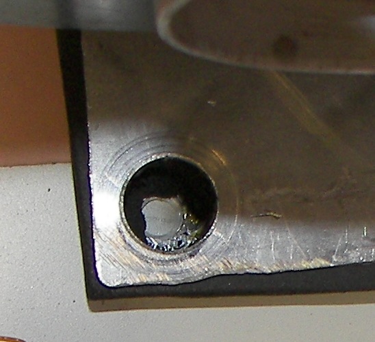
Capacitor mountings are home-made. The top section comes out from the cap body so the bolt heads don't put pressure on the case. At the bottom, a small piece of 1/8" thick plastic, originally a junction box cover, protects the capacitor case. "Lag Bolts" with fender washers fasten this to the rack floorboards. Note the angle iron across the front. This has several lag bolts through it and serves to bind the two 2x10 planks into one solid floorboard. |
|

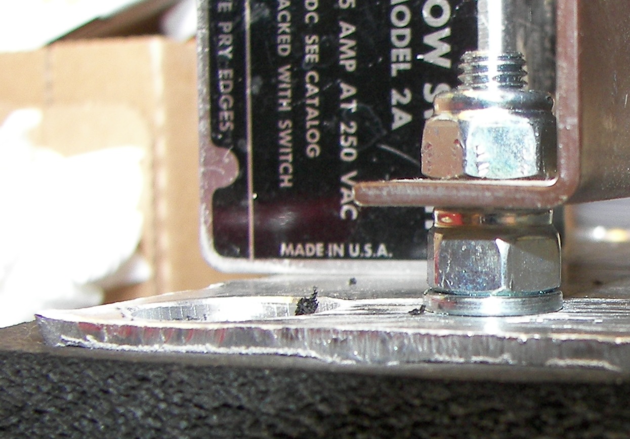
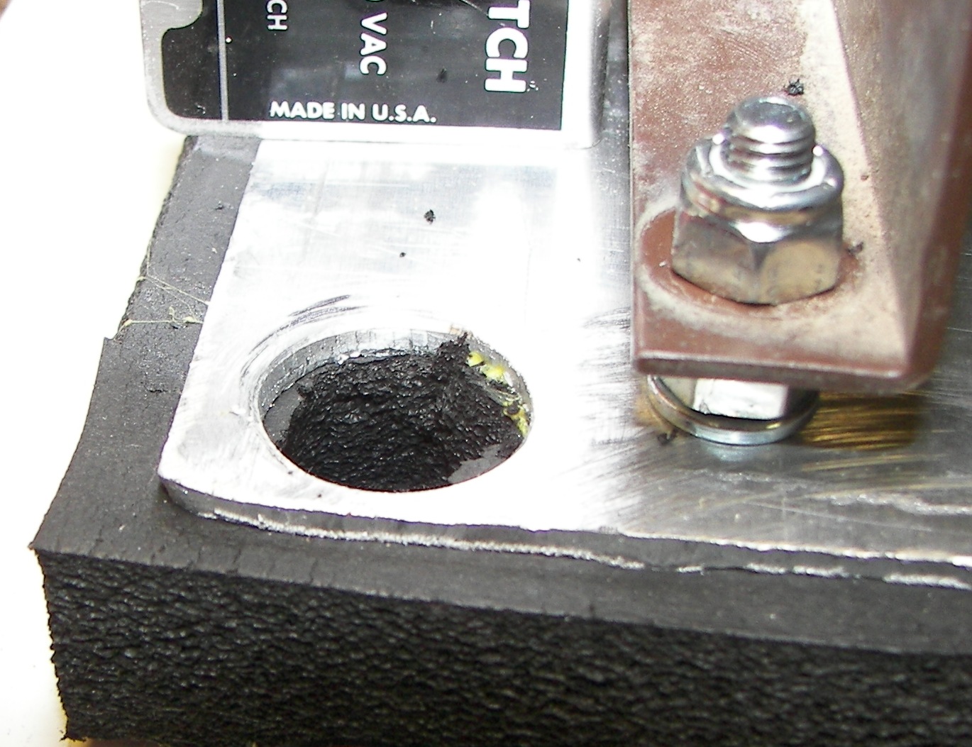
A single larger bolt, 1/4", secures the lower end of the capacitor bracket. A 'nylock' nut is used. Lag bolts fasten this to the rack floorboard. |
The choke is mounted with a metal strap and lag bolts, Note the washers under the strap that equalize the height of the strap across the choke's mounting flange. This was done because the holes in the choke's mounting flange were very close to the easily damaged winding and the lag bolts are 1.5" long. OK well nothing's going anywhere. |

The blower anti-vibration mount is also home-made. It's a piece of pliable closed-cell commercial foam rubber 3/4" thick. It is sandwiched between two 1/16" aluminum plates and glued. |
The air switch also needs some work. A paper clip was partly unbent, and one end beaten flat so it would fit in the tiny slot in the switch actuating axle.Rather than soldering it and risking damage, some metal epoxy was used. |
The anti-vibration mount top has large holes to allow a socket to fit in, and the bottom plate has 1/4" holes to admit lag bolt threads, which go into the wood floor. |
This way, the bottom side is firmly attached to the equipment, but the top plate and blower are free to vibrate without transmitting the usual humming and other noises to the structore of the cabinet. |
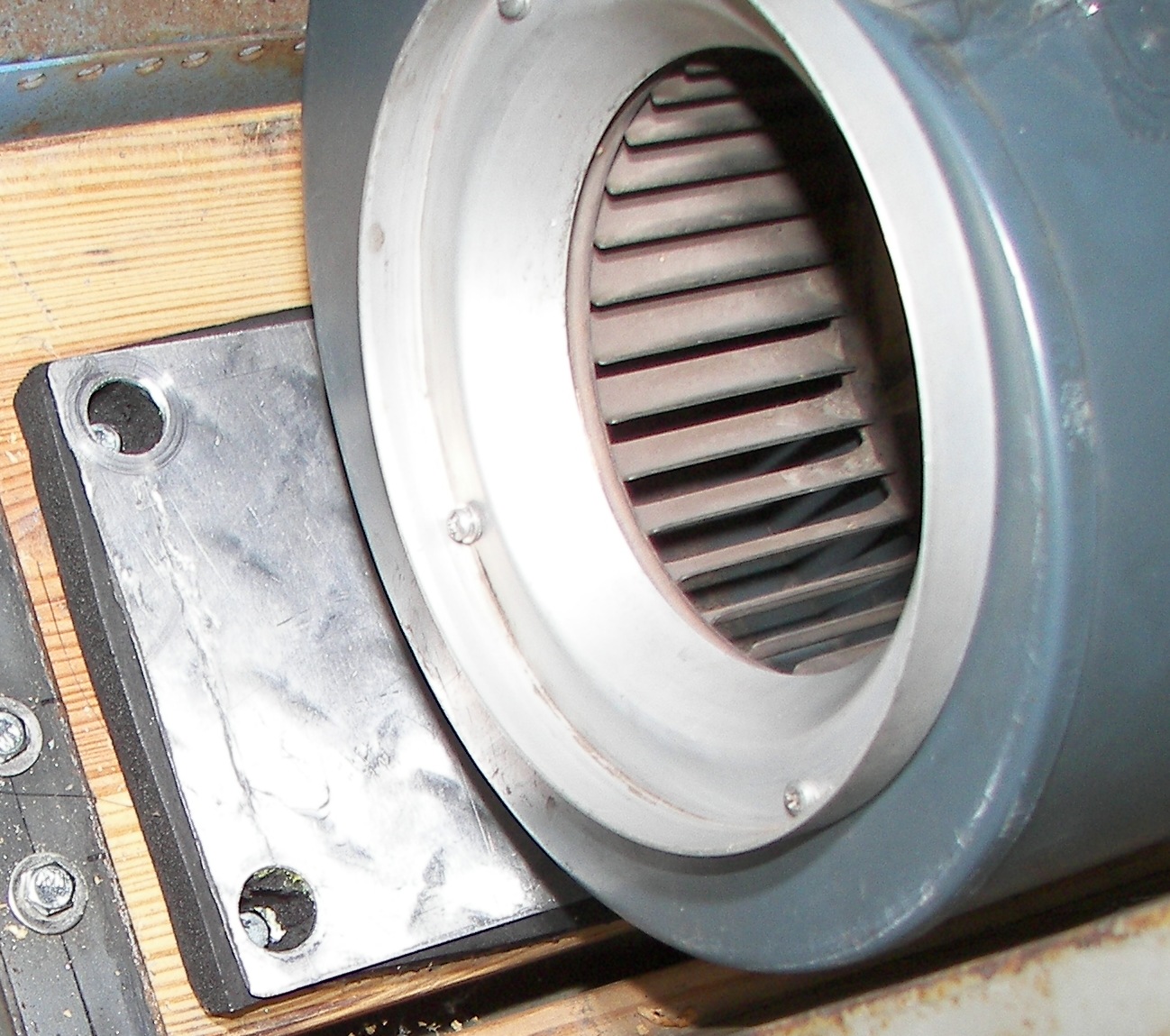
The blower already has provision for an air switch. |
The blower mounts to studs. These are 1.5" long 1/4" bolts that come up from the underside of the top plate (isolated from the bottom plate by the foam rubber) and are secured by a lockwasher and tightly fastened bolt (this is where Grade 5 hardware is important - no snapping off the heads of a cheap bolt). Once the blower is in place, a nylock nut holds it. A lockwasher underneath the blower's bracket adds some tension to keep things tight, but is not there to resist turning. |
These holes are kind of tight to the socket size. but they do fit. Works fine! |
A ground cable is made for the blower. It could have been made as part of the blower AC cord, but this was as well. Every single ring connector in this project is not only crimped, but well-soldered. There are no bad connections wanted. Unless there is a definite reason to avoid the heat, it's just lazy not to solder this kind of crimp-on connector in my opinion. This one looks ugly but it is definitely very strong and not going to pull apart. |

|
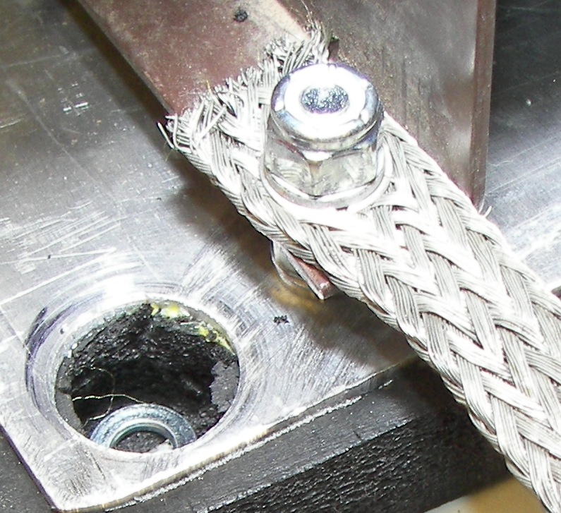
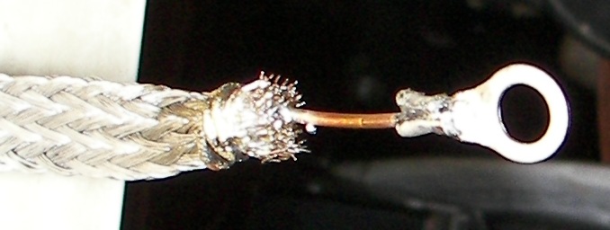
The ground strap nicely had eyelets in it - Nice! The other end goes to the rack frame GND. |
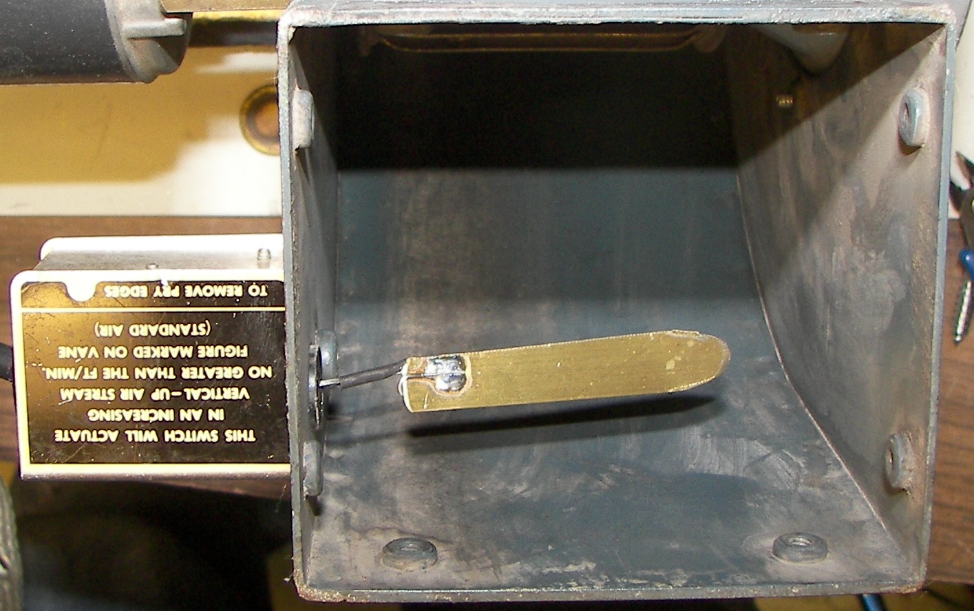
A nice little vane was made of brass and soldered to the paper clip. Many paper clips are nickel plated and can take solder decently with some heat and generous rosin flux. |
Bolted in pace. |
The additional connector carries the wiring from the air switch to the 'electric brain' of the amplifier. No air=no filaments. |
|
|
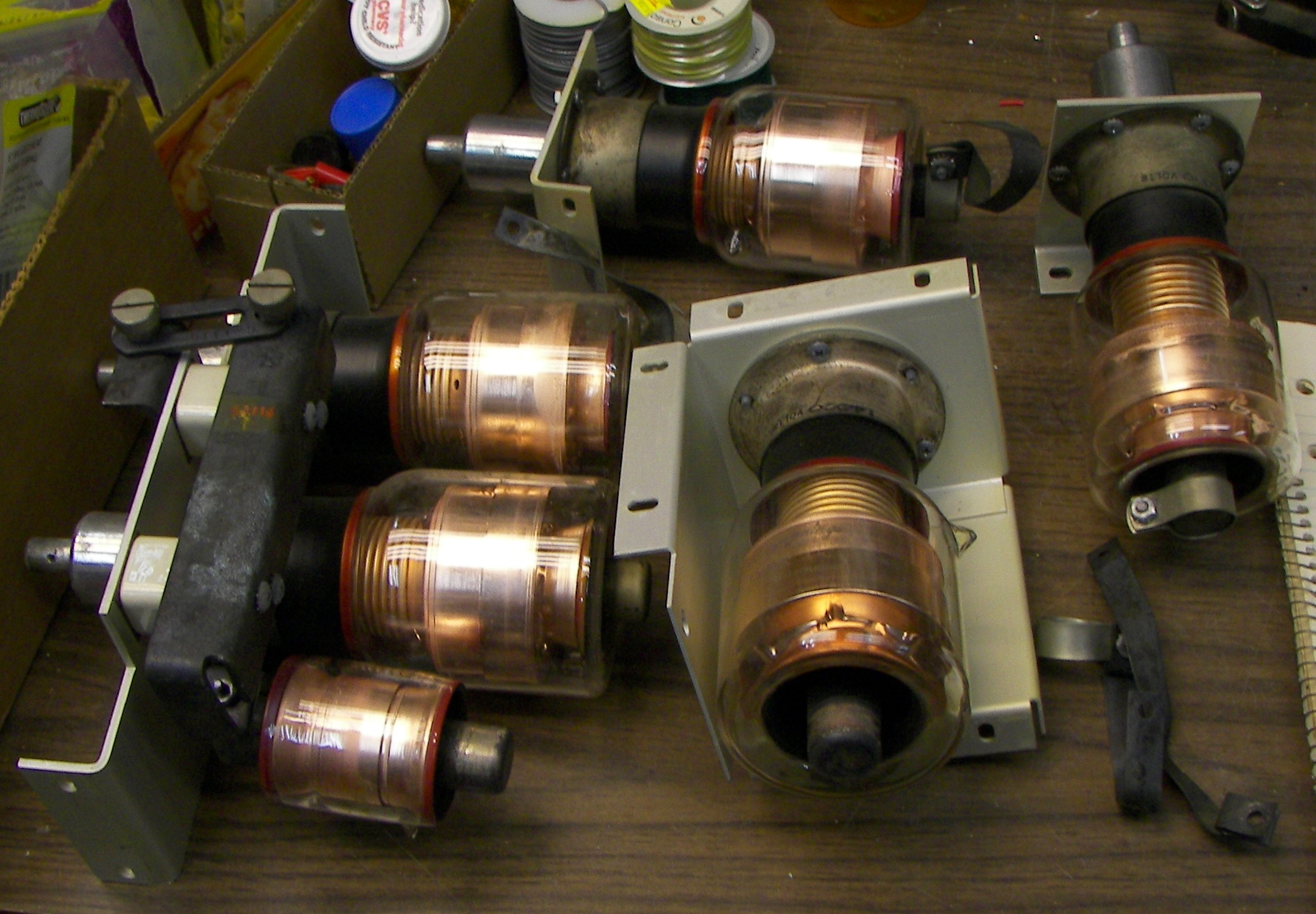
Some vacuum variable caps showed up - 750pF. Not yet sure how to use. |
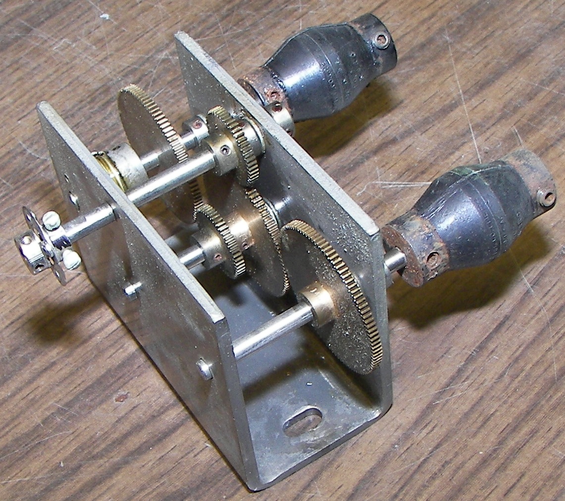
This set of gears may also be useful. It would be nice to have one crank to tune the cathode circuit through the entire HF band. |
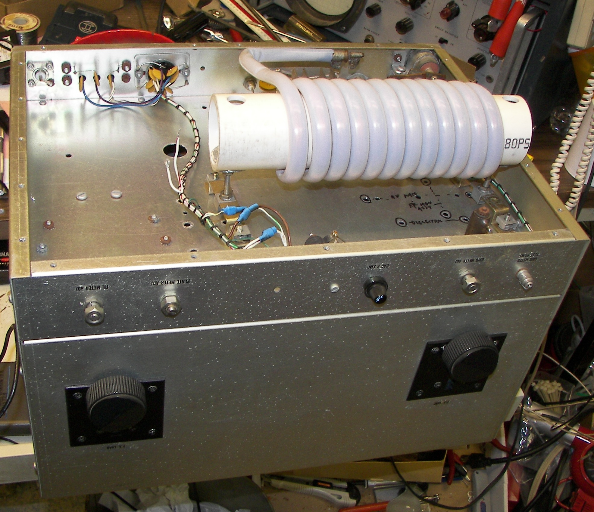
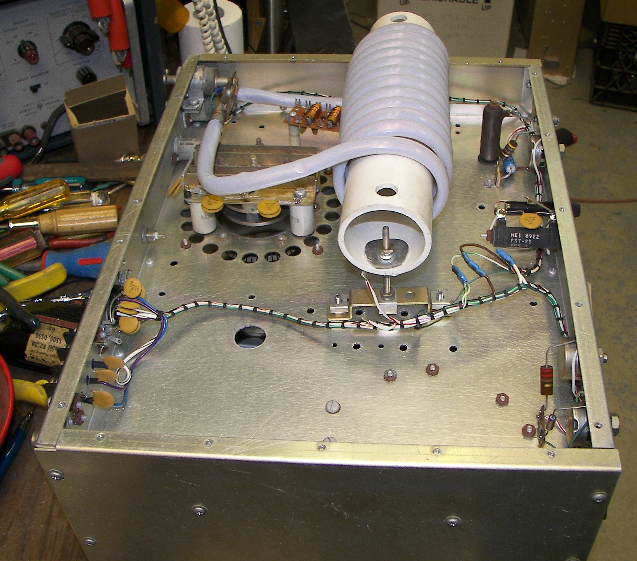
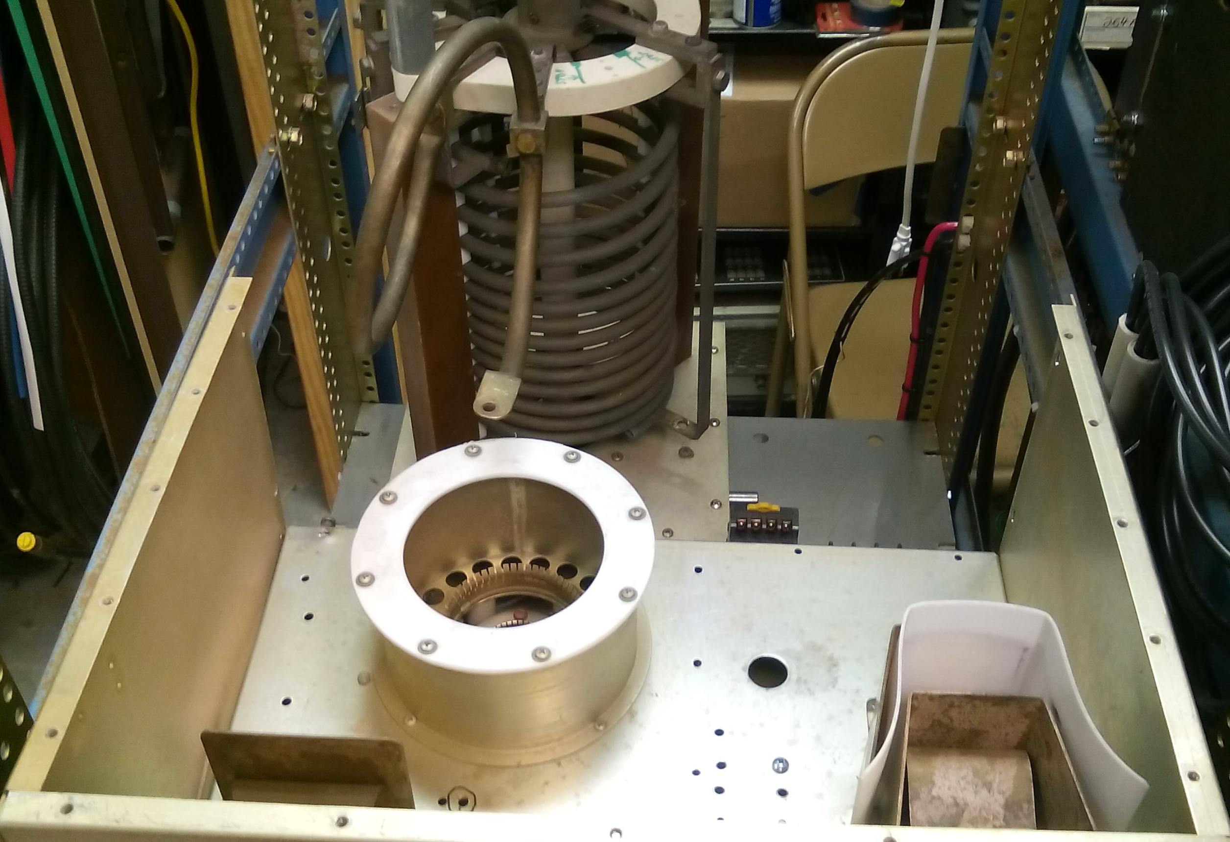
With the power supply and blower pretty much squared away, time to look at the RF deck. It's a Henry RF generator, 2KW, having the right socket and many useful parts. This is the underside. The '14MHz ISM' Cathode choke has to be replaced with a higher inductance unit. |
This small board is part of the filament voltage measuring circuit. It's best to measure the voltage at the tube socket like this. The board contains a rectifier and filters so that the meter need be just a DC instrument. |
The original cathode matching circuit will be removed. |
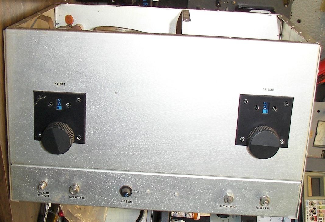
Front of the Harris chassis. |
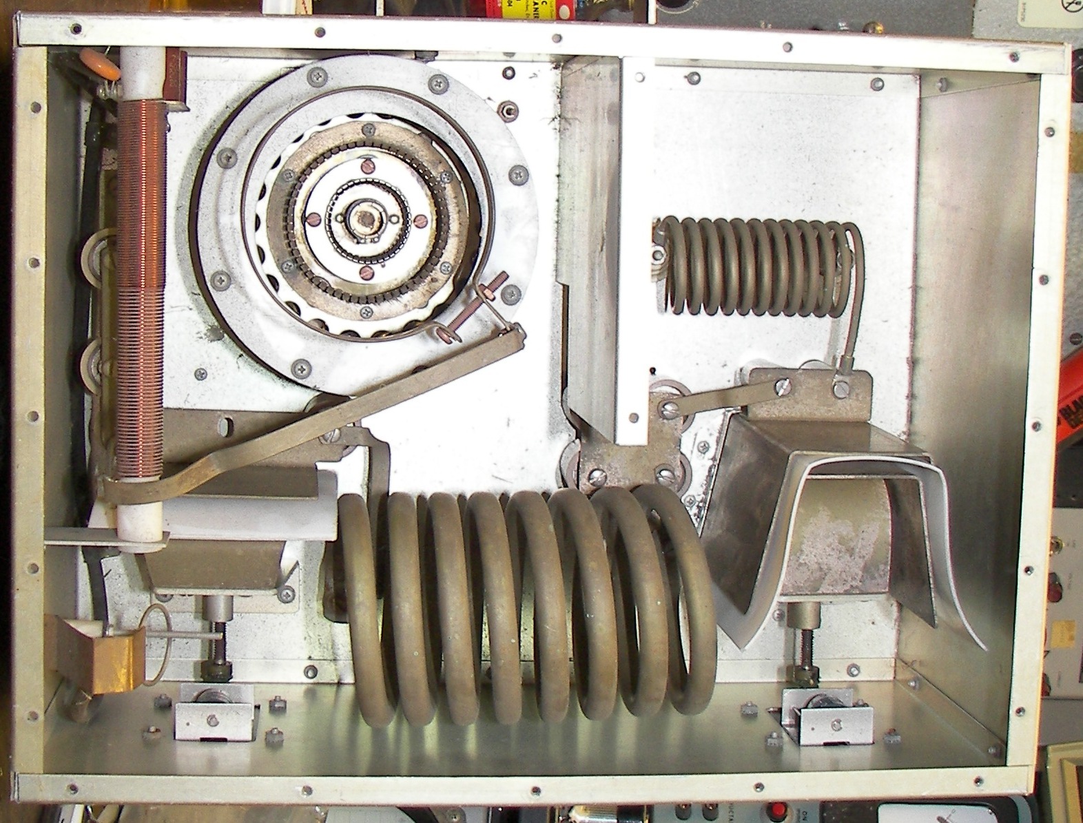
Top view showing the tuning capacitors with their Teflon dielectric, Plate coils for the PI, and L sections, RF choke, and several "doorknob" capacitors. The ingeniously made HV shorting interlock is at the lower left. This will probably be removed as the chassis is going to be modified and will not have a top. The plate choke has not been checked for resonances or value but is likely too low inductance for 160 Meter ham use. The turns counters are worth saving as well. |
The 7/8" Bird 4522-002-5 directional coupler was removed from the back of the chassis. It is just adequate for the power level and the connectors will need to be changed to larger sizes like the DIN 7/16. It takes '43' elements. |
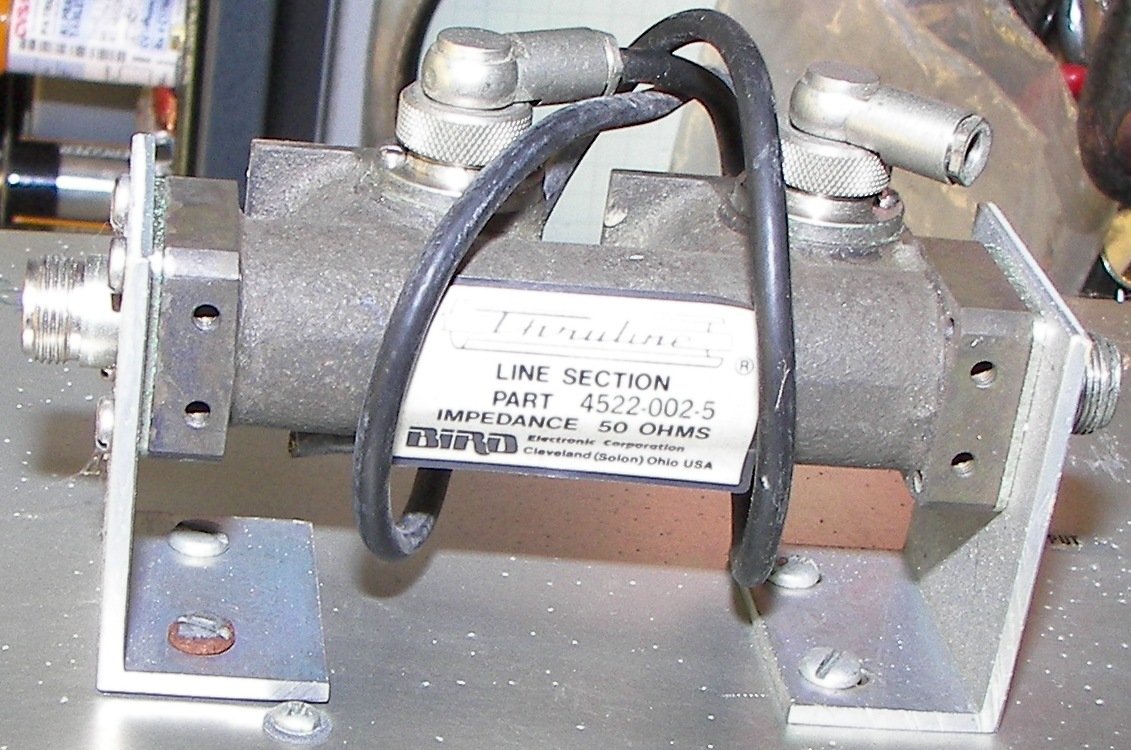
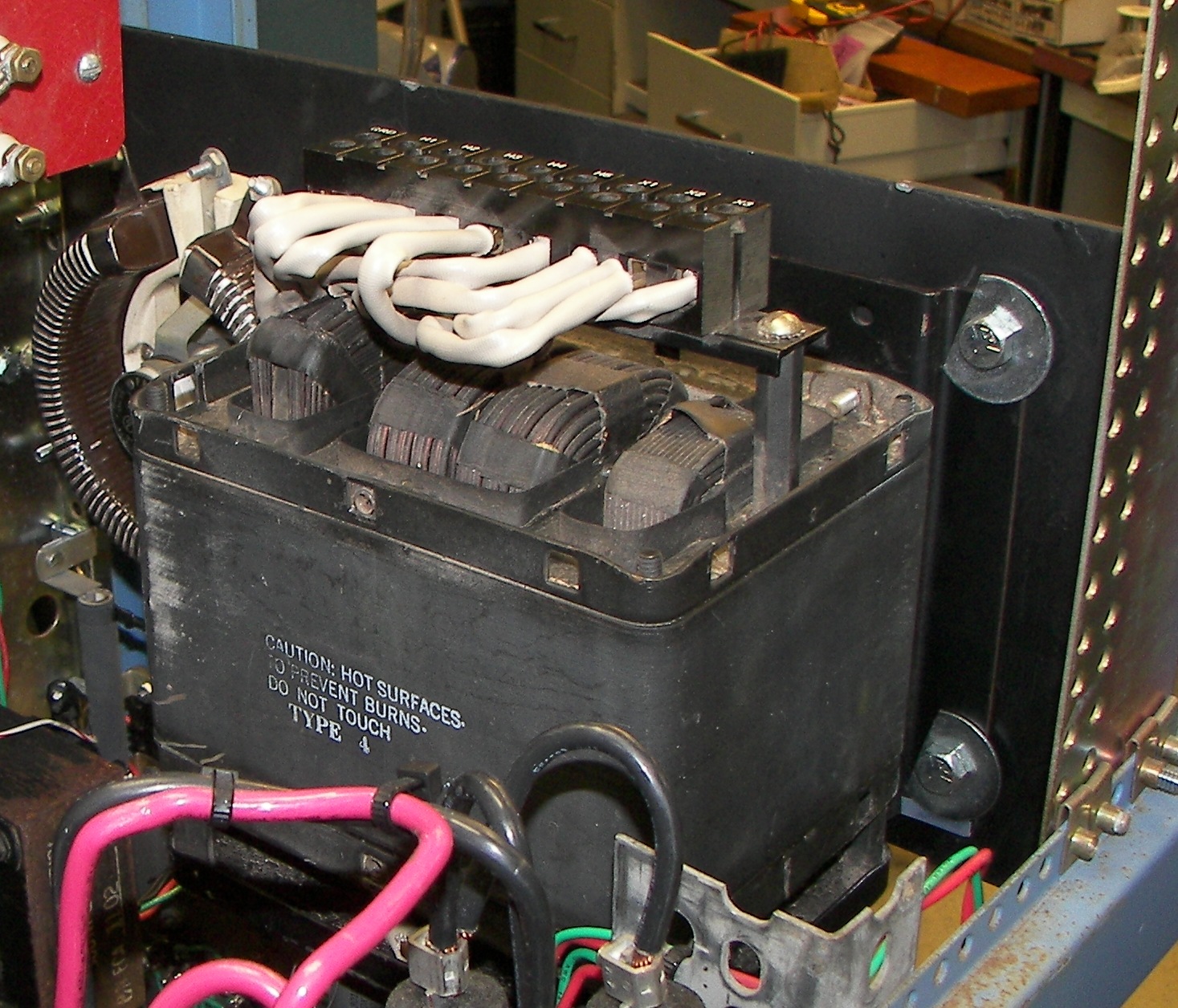
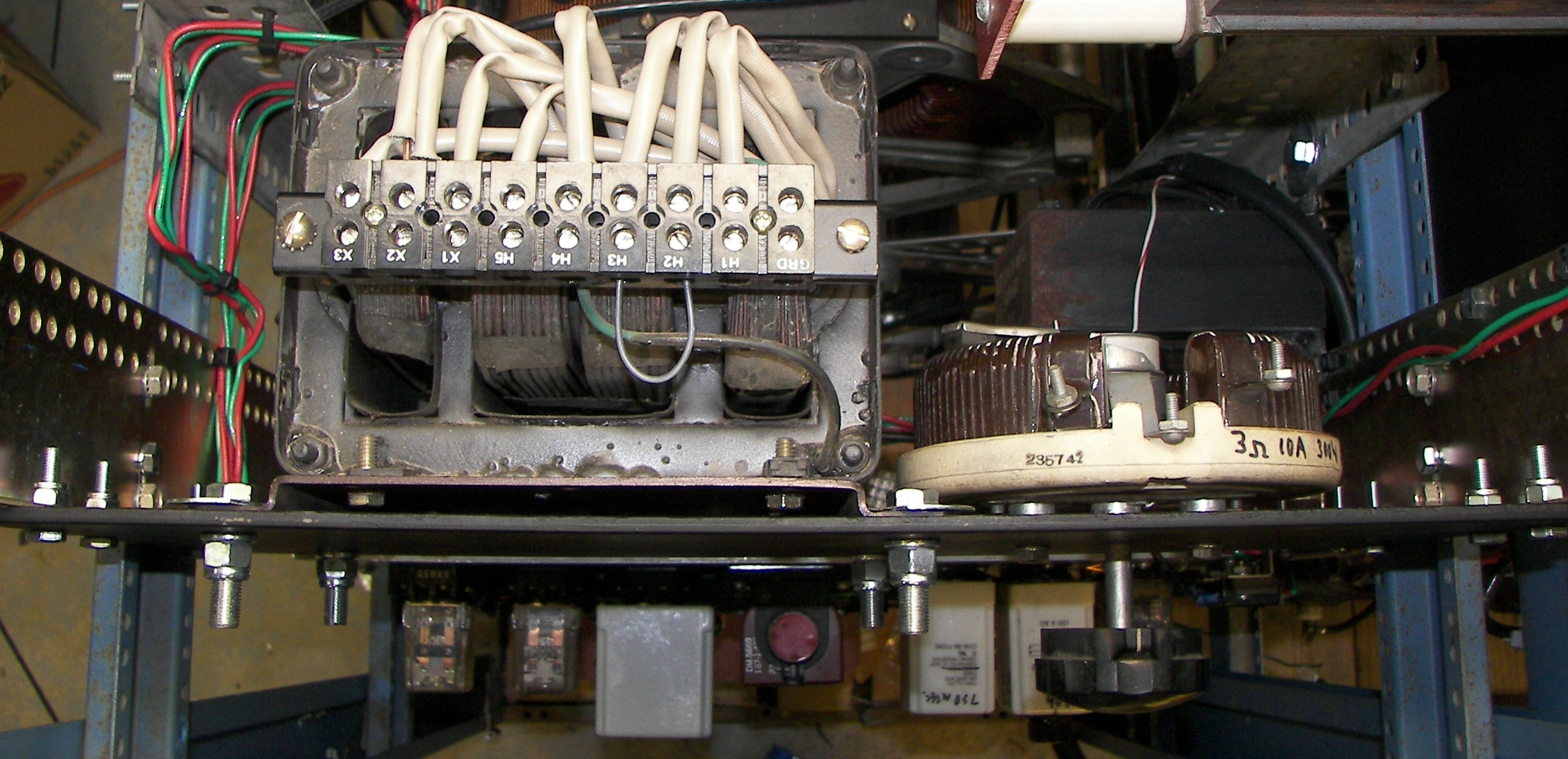
Filament transformer for 3CX3000 from the harris RF generator. ECA1102 PRI: 208/220/230/240VAC SEC:7.5V@52A with 10 Ohm 50W series resistor which was that unit's filament inrush protection. |
|
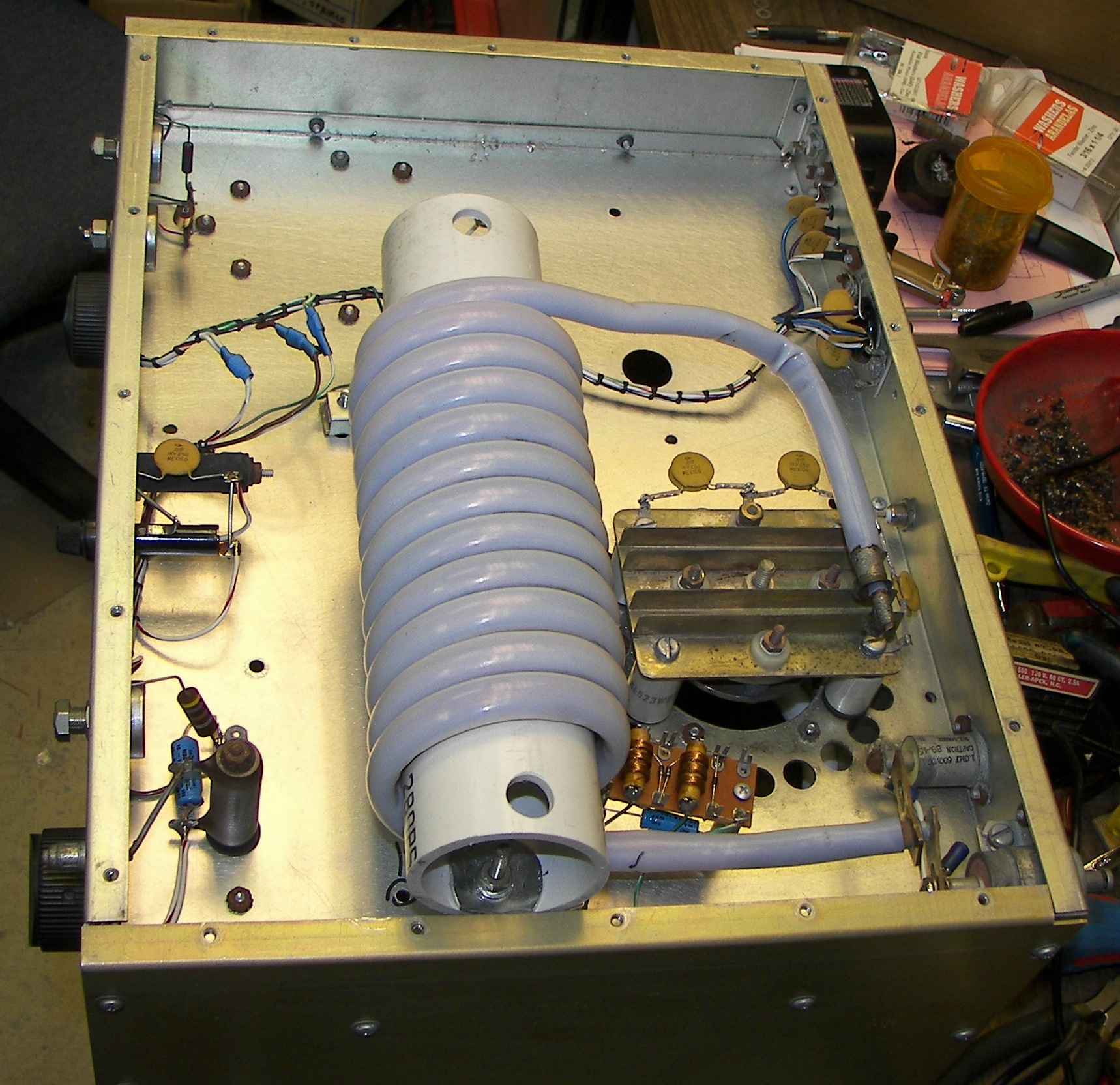
Likely to be used in plate circuit. |

Likely to be used in plate circuit. TMC GPT-10K plate coil. 2-30MHz bandswitched PI coil from 10KW 4CX5000 GG linear amplifier stage, designed to be run at +7500V above ground. The best thing about running the PI coil at HV is that the RF plate choke is much less critical since the vast majority of RF is across the PI coil. |
Filament choke from same TMC GPT-10K 10KW amplifier. It's designed for 2-30MHz. |
The PVC pipe holding the choke is mounted with stout brackets. Large fender washers were trimmed and bent to fit the curve of the PVC pipe. Cut-washers (lockwashers) were used throughout on this assembly. |
Choke is much larger than original single band choke. |
|
upside down view of chassis A 4" deep aluminum chassis is the perfect size to extend the bottom of the Harris chassis so that the RF choke is enclosed and has plenty of room. There should also be room for a variable capacitor and inductor inside for cathode tuning/flywheel. The area must be enclosed for air as well as RF because it will be the 'wind chest' for the 3CX3000 cooling air. A hole may be cut in the side or bottom to connect the duct from the blower. Right now a simple method of disconnecting and reconnecting the air duct in a sealed manner is being sought, the idea being ease of service. On the othe rhand, if the circuitry is built well service should not be needed often! |
|
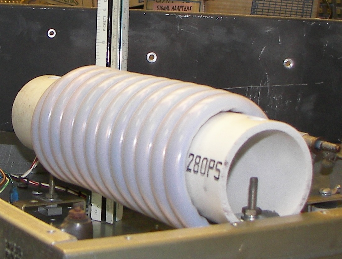
Six large ferrite rods were needed to increase the inductance of the filament choke for this amplifier's purpose. It worked in the previous amplifier driven by a 1KW stage in a special circuit where high inductance was not called for. |
The ferrite rods were longer than the previous PVC pipe. There was no way to easily cut the rods so it was best to make the pipe longer and move the end mount. |
The connection from the hot end of the choke looks ugly but is electrically and mechanically solid. |

The cold end was pretty simple to screw directly to the filament choke bypass capacitors. |
|
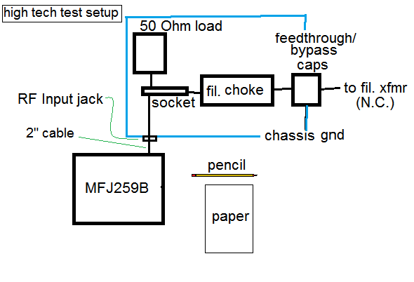
The RF choke setup was checked in the chassis with a 50 Ohm load attached to the tube socket. The tube driving impedance is very close to 50 ohms. |

The curves show the test results. It looks very satisfactory. Some have built amplifiers without tuned cathode circuits, and other claim that when a solid state driver is used, a tuned circuit is more important because there is no "resonant tank circuit" nearby to smooth the drive voltage waveform and make distortion lower. It's worth it to use a tuned circuit, at least a parallel LC circuit if not a PI network. |
It was decided to go with a regulated filament supply. The mains voltage here varies quite a bit in the Summer due to air conditioning loads and is generally high in Winter. This means 220-250VAC, translating to a 7.05V to 7.95V variation in filament voltage (0.9V difference). Eimac specifies maximum limits as 7.12V to 7.87V |
Most people either don't worry about it or they use a rheostat or variable autotransformer and manually adjust the voltage to 7.5V as required. Issues with this are that when the HVAC cuts on or off, not to mention when the substantioal amplifier is keyed, the voltage will go out of specification, and this may happen frequently. It would mean constantly having to watch and adjust the filament voltage. The SOLA regulator's covers were removed for better cooling and easy access. |

A SOLA 1KVA low-harmonic ferroresonant regulator was installed to a thick steel panel. In conjunction with a 3 Ohm rheostat this will hopefully allow the filament voltage to be precisely set and remain regulated under all but the most extreme conditions. The panel is attached with six fine thread Grade 5 fasteners and Nylock nuts. The regulator is attached with similar 3/8" fasteners. |
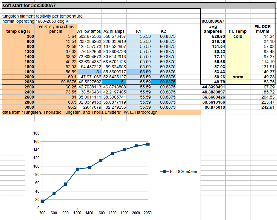
A study was made to estimate the constants needed for the best value of inrush-limiting resistance to be used with the 3CX3000 Filament. The filament is essentially Tungsten and the resistivity is discussed in a couple of volumes. |
A 90 ohm resistance may be appropriate to limit the filament cold current to about twice the hot value. |
In the meantime, the plate supply inrush limiting resistance was changed from the initial testing value to 10 Ohms. The inrush to charge the filter will be limited to about half the full load current. |
|
Just seeing how things fit. The amplifier chassis will sit on a couple of metal plates. It is also decided to hinge the lower section so that it can be opened for service yet also be used to mount certain items like the filament tank circuit, etc. A strip of RF gasket around the seam can seal it. If too much air leaks, some aluminum tape is easily applied around the seam. |
|
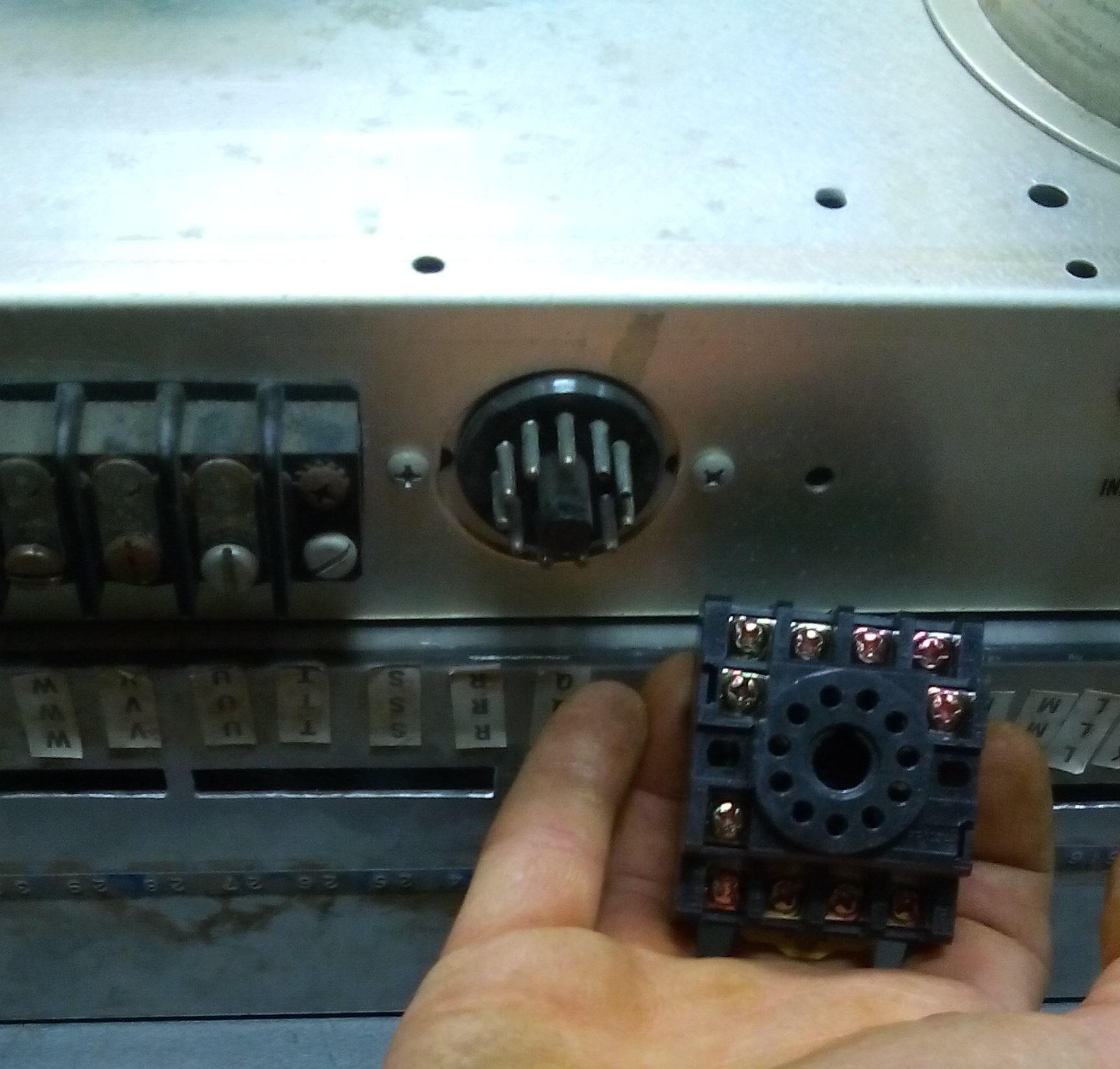
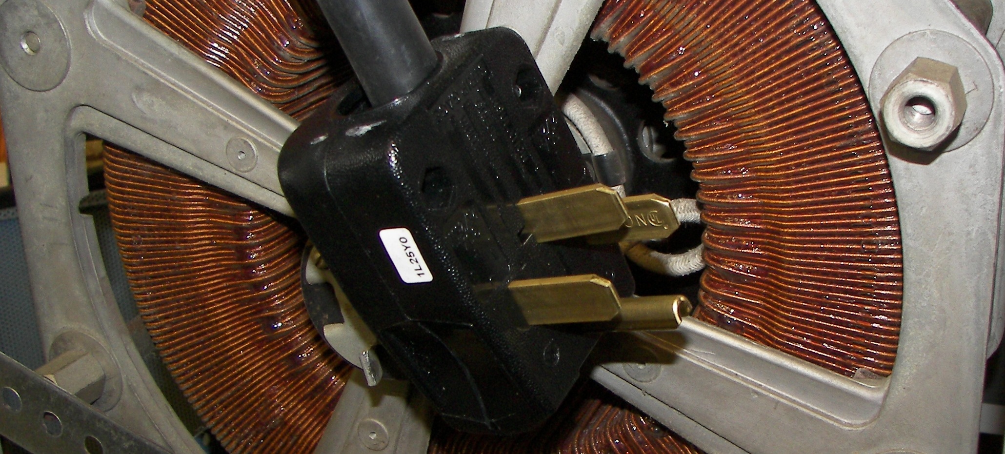
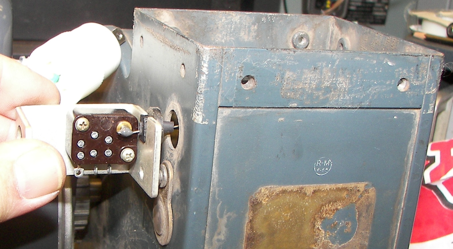
Plug and socket for control and metering. Not yet decided, but it may be as well to minimize measurement-related items inside the chassis. An arc-over often destroys them. |

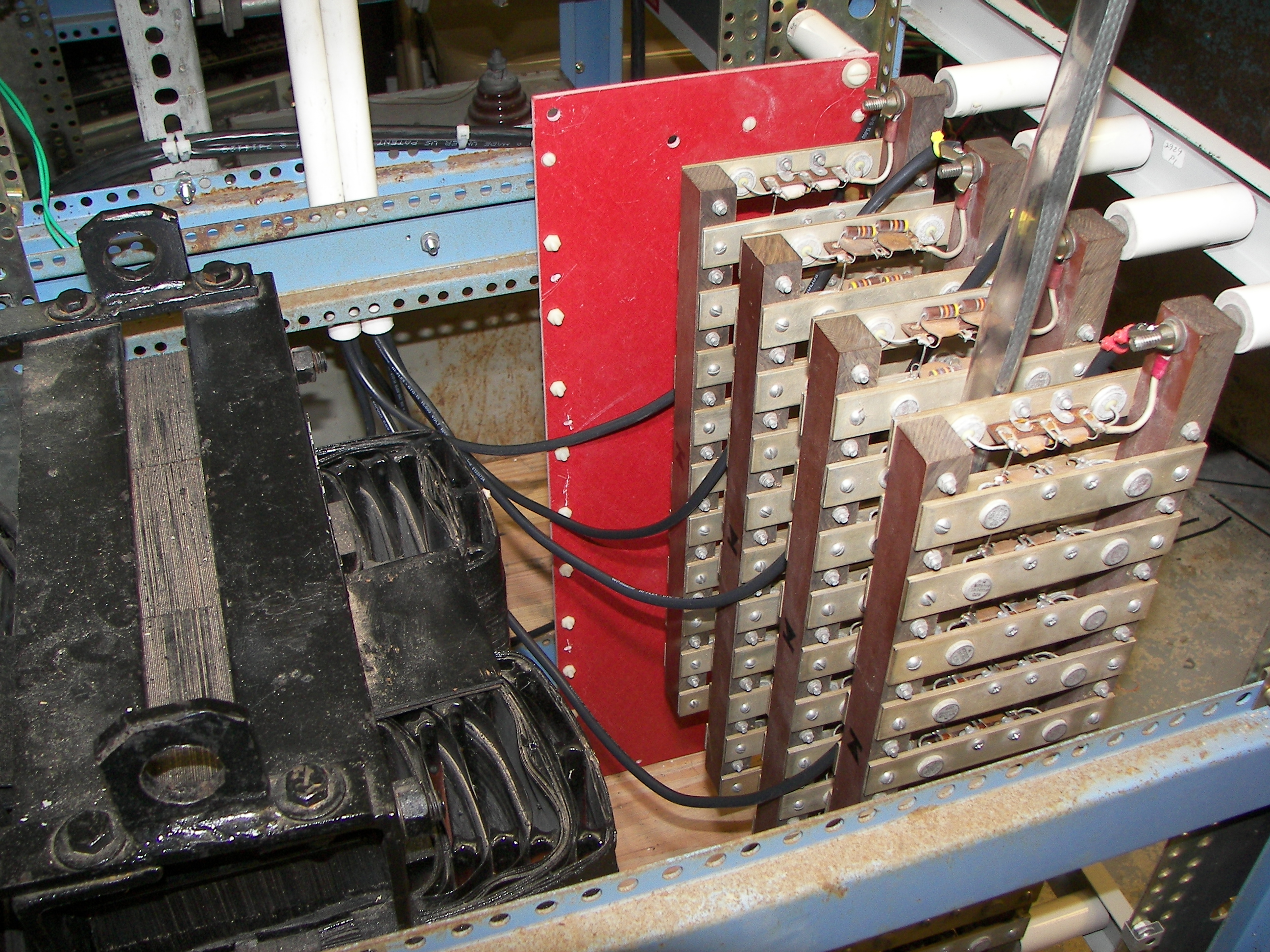
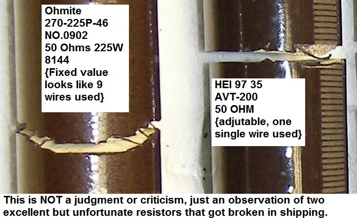
50 Ohm 225W resistors - candidates for a glitch resistor bank. Some HV might be lost here but limiting the arc current is important when there is a 31uF capacitor feeding it. |

Some were cracked when arrived. Note the differences in construction. |
|
|

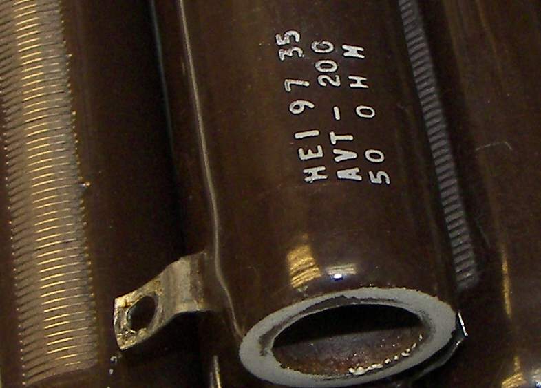
HEI resistor data sheet |

|

Ohmite resistor data sheet |
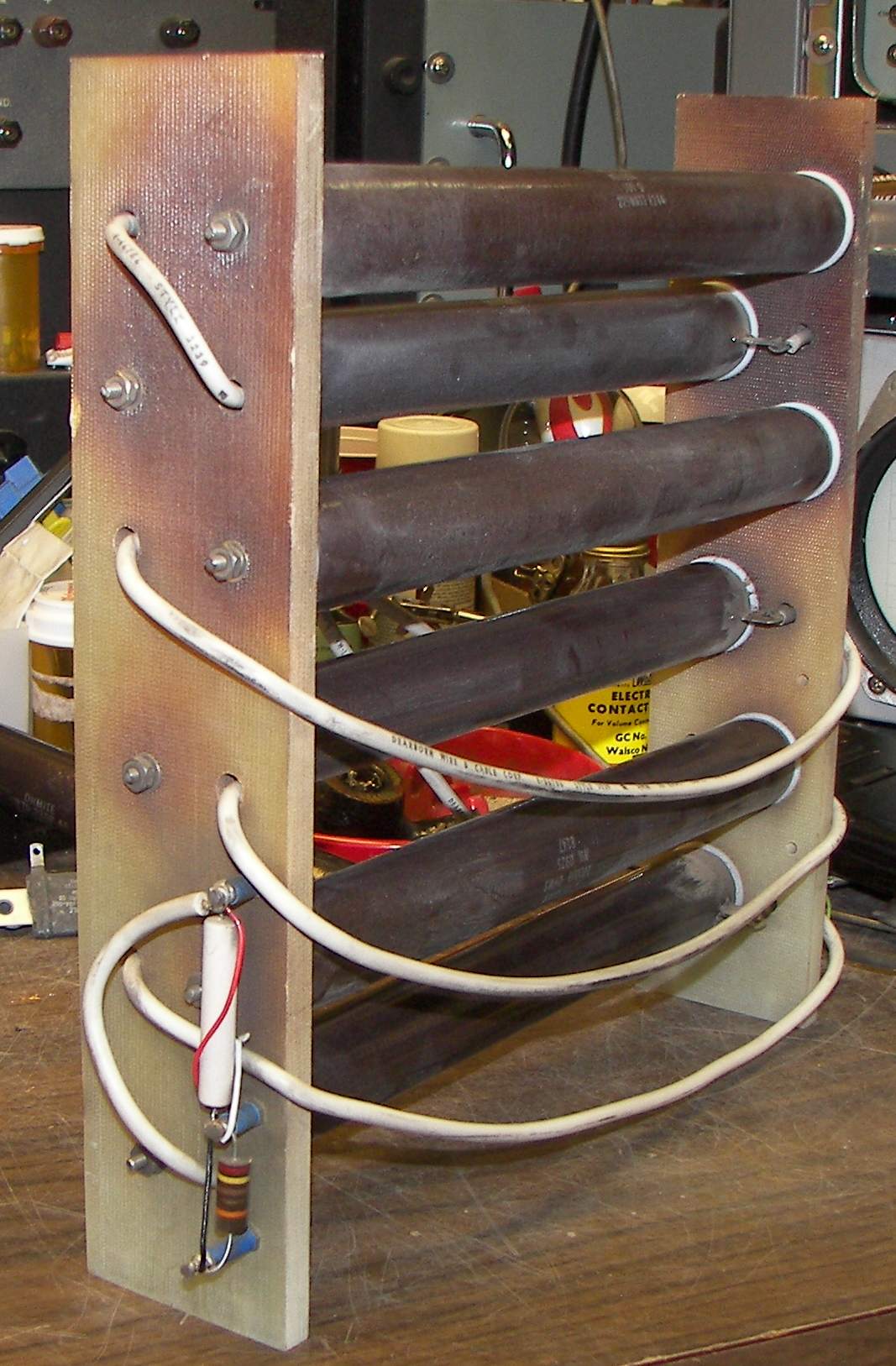
The glitch resistor bank will be built on this salvaged bleeder assembly. |
|
|

|
|
More to come...