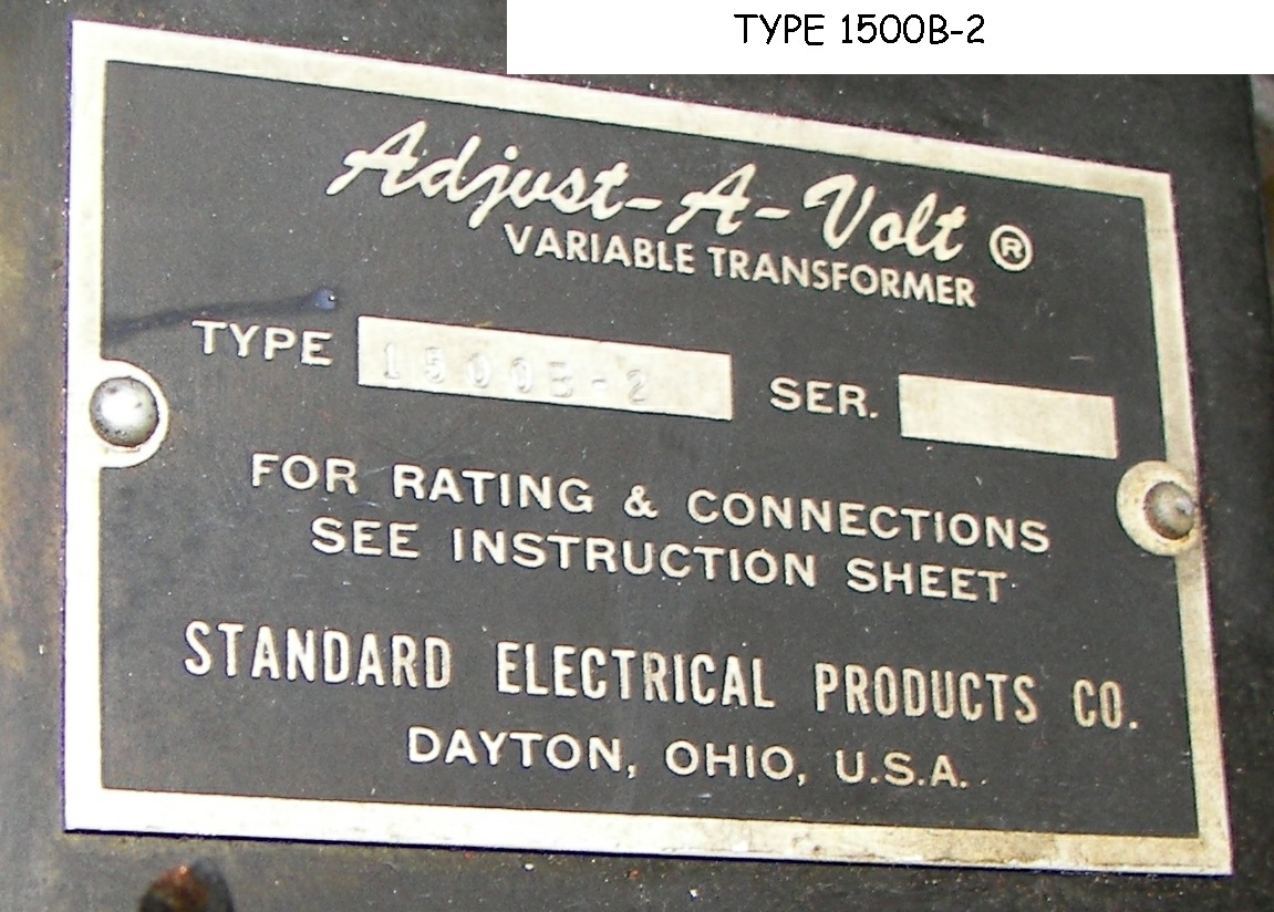
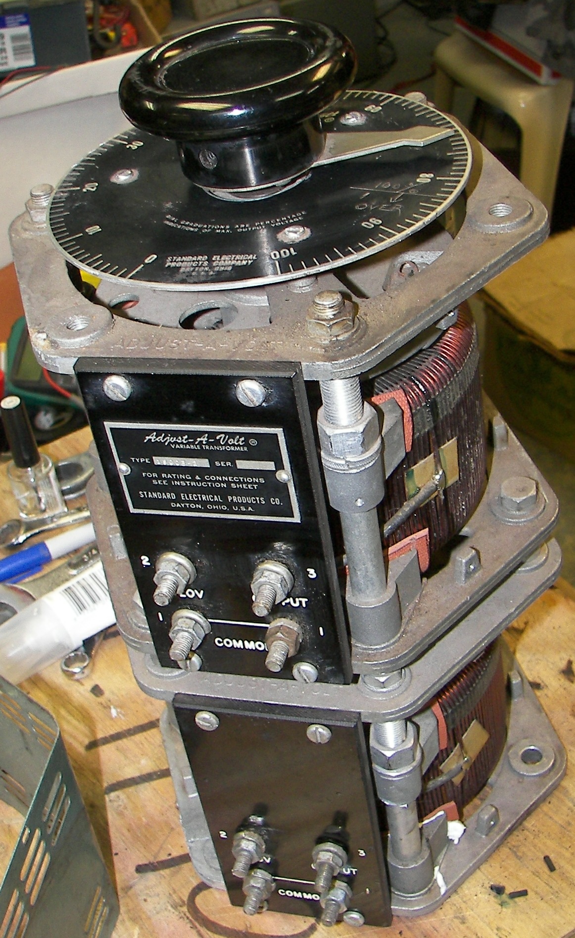
Model 1500B-2 is a dual 0-140V 1500VA unit. It can also be used to control both sides of a 240VAC circuit, for 0-280V input to a 3000VA load. As with most variable autotransformers, substantial overloads are tolerated for short time periods without damage and good regulation is maintained.
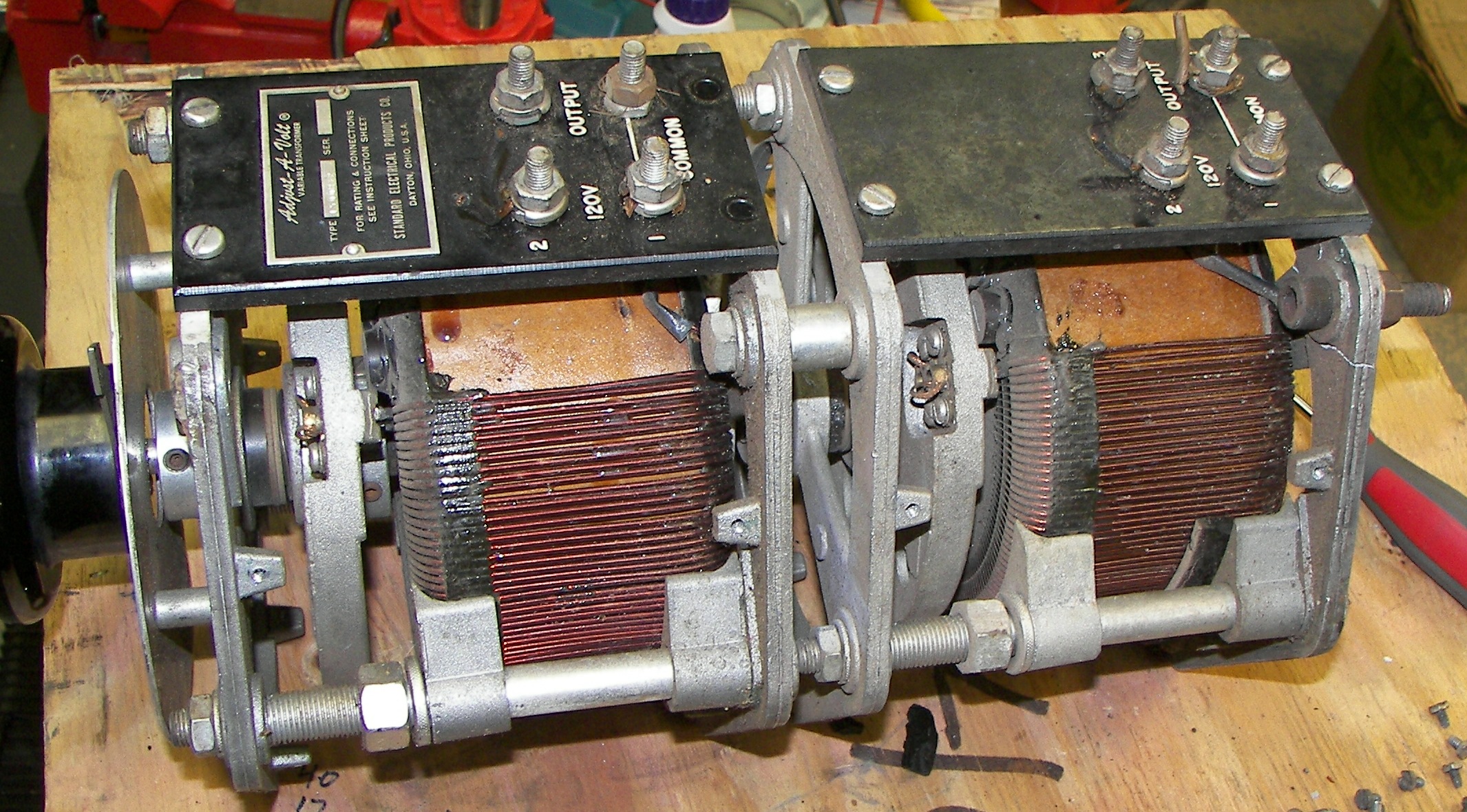
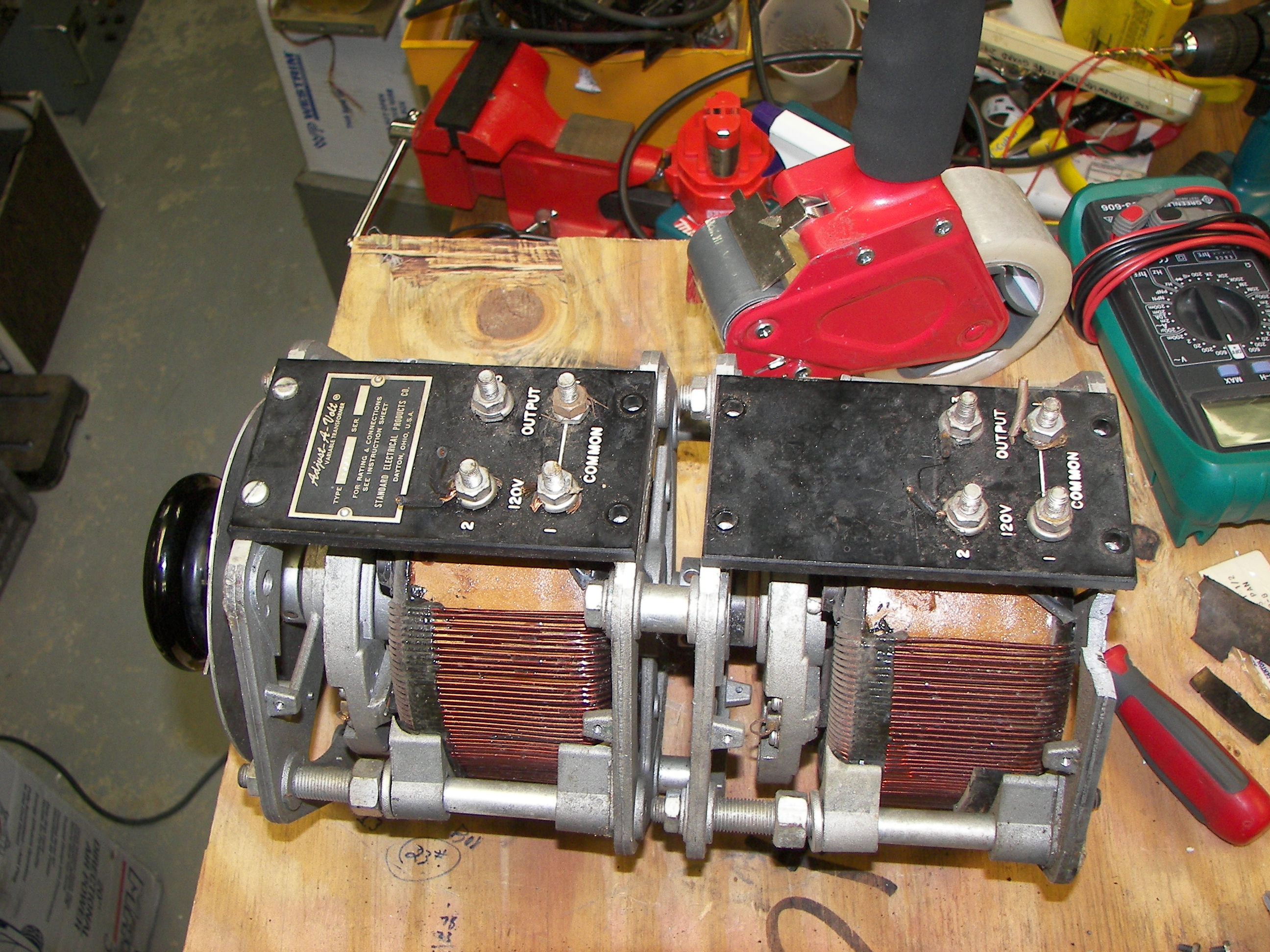
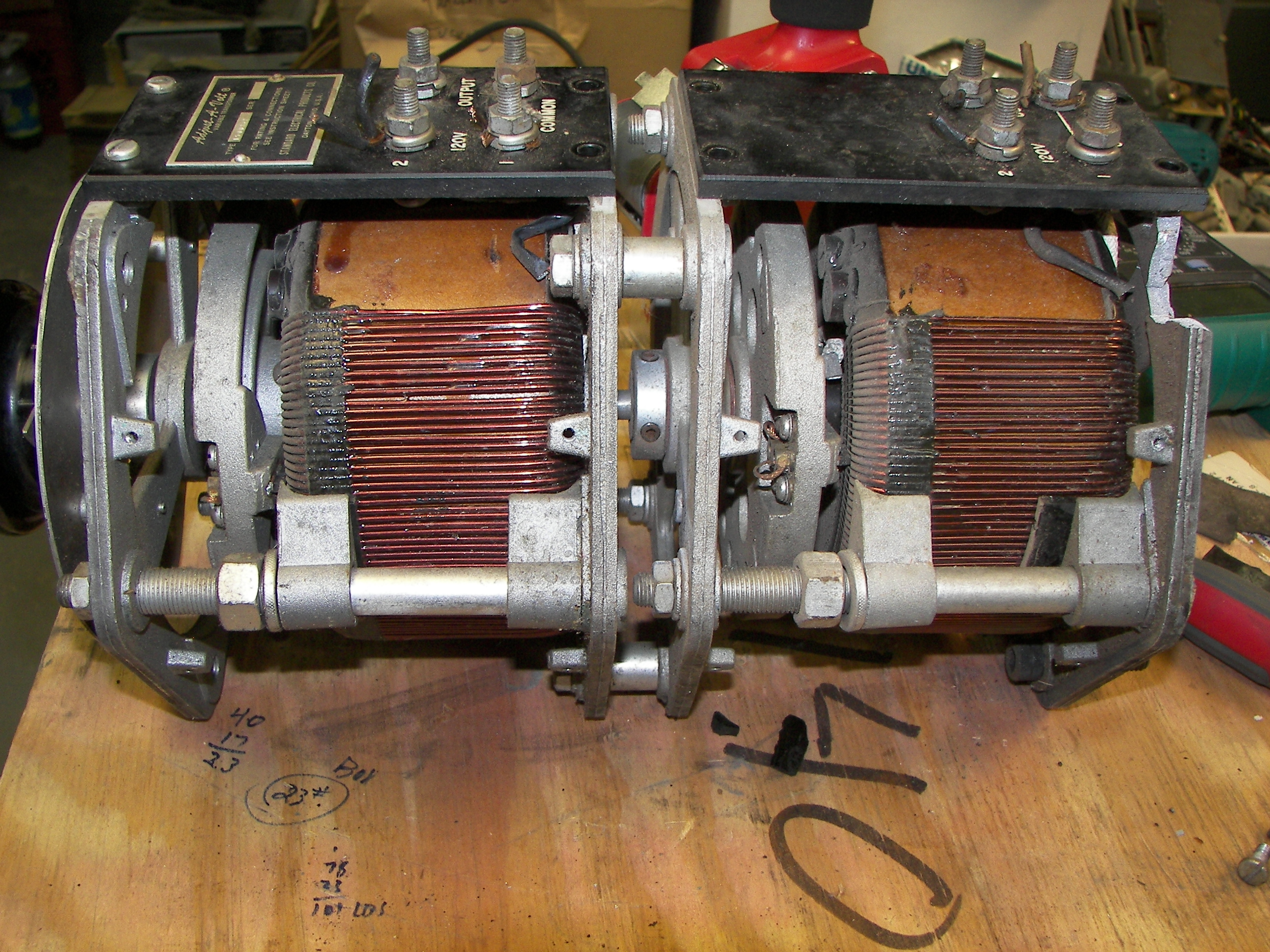
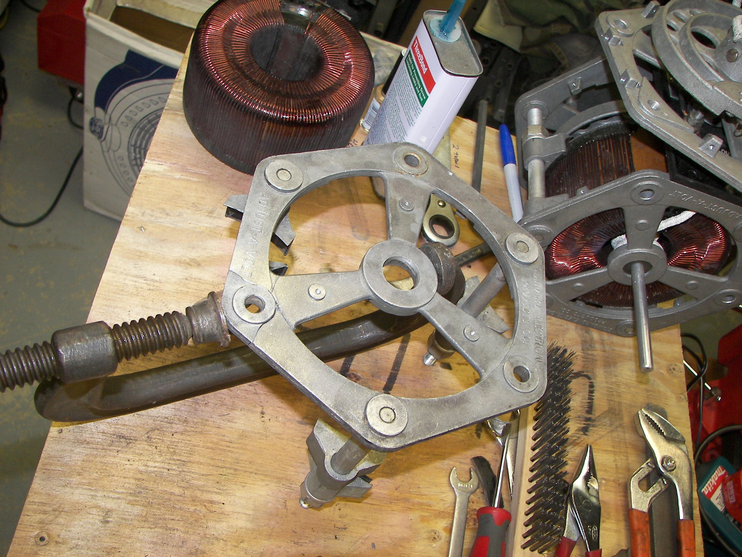
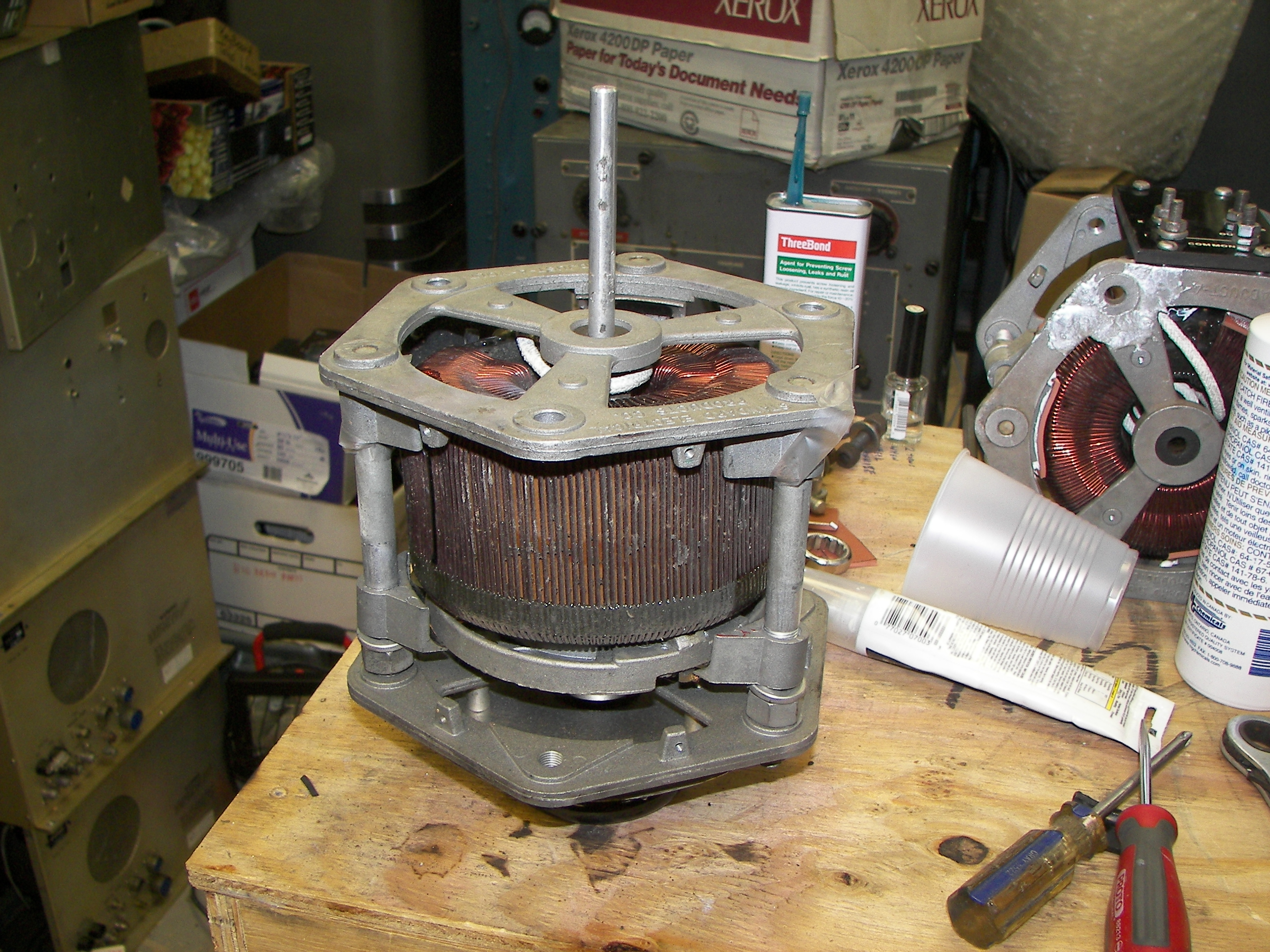
The unit ready for inspection before disassembly and repair.
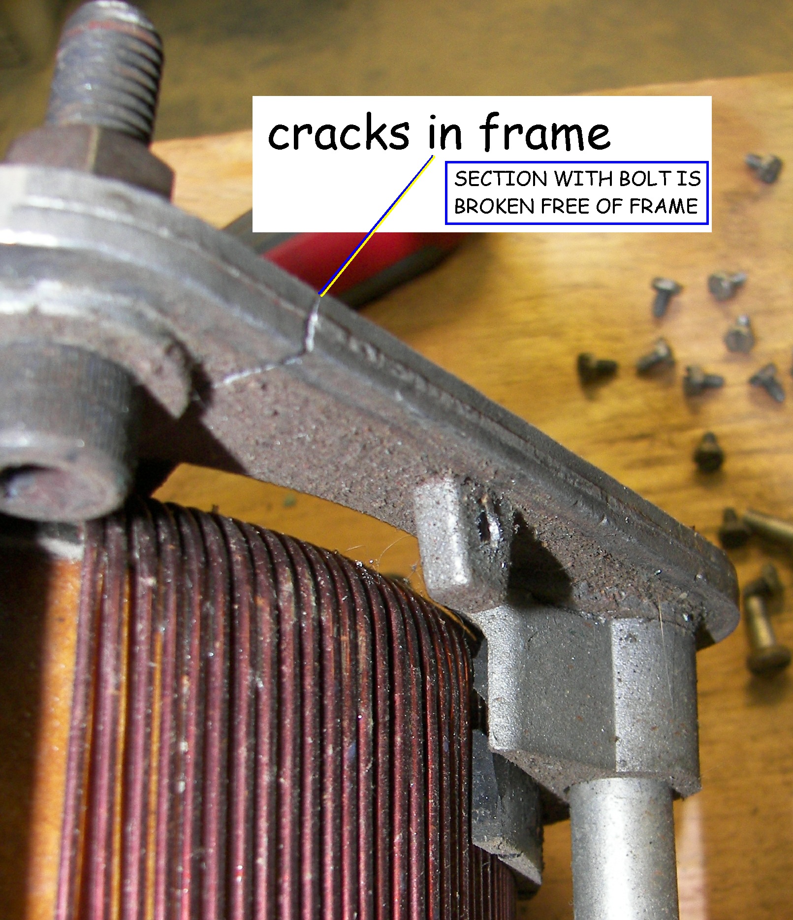
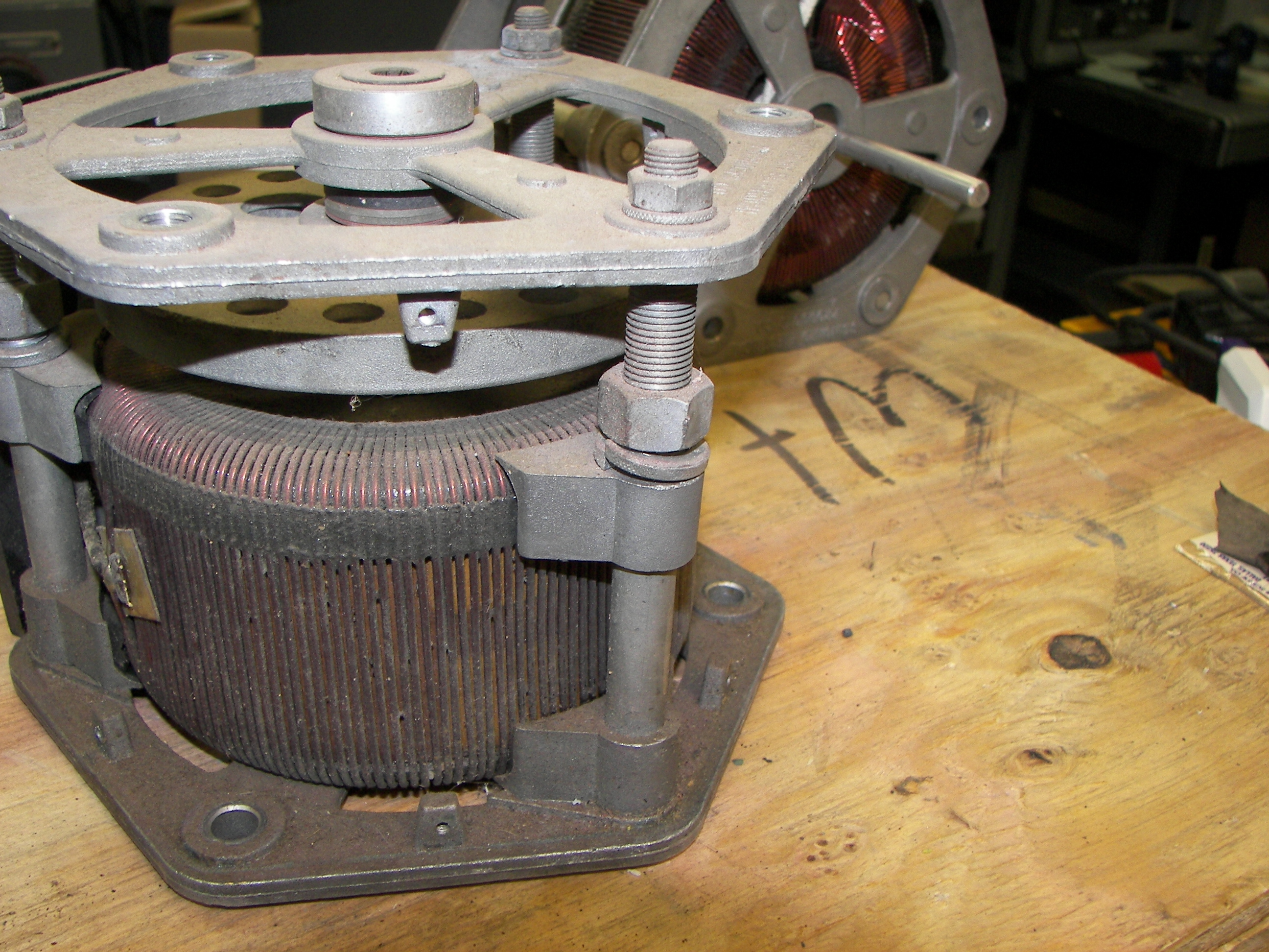
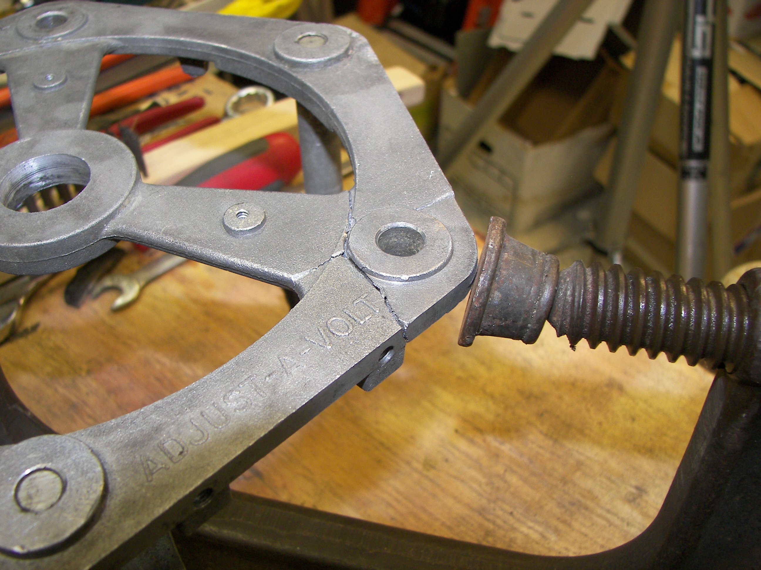
This crack in the frame is from the unit being dropped.


The damage is severe, the now unavailable plate would have been replaced back in the day.
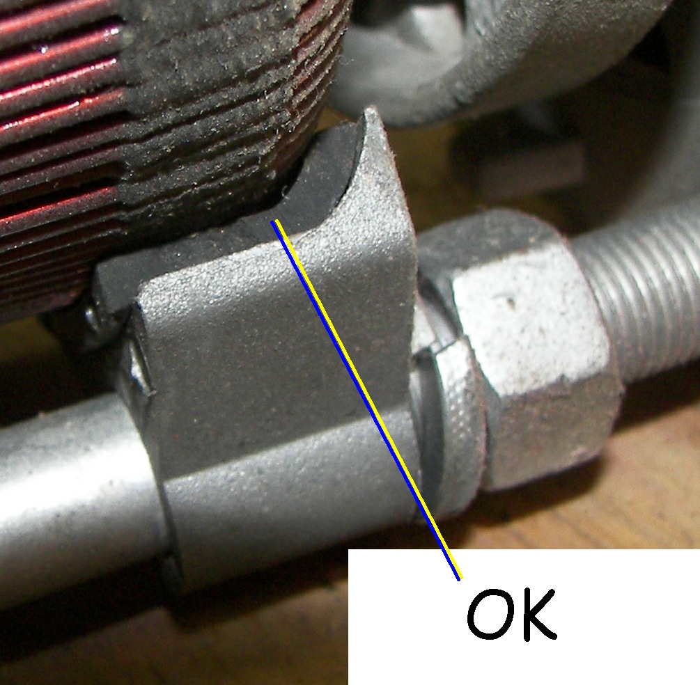
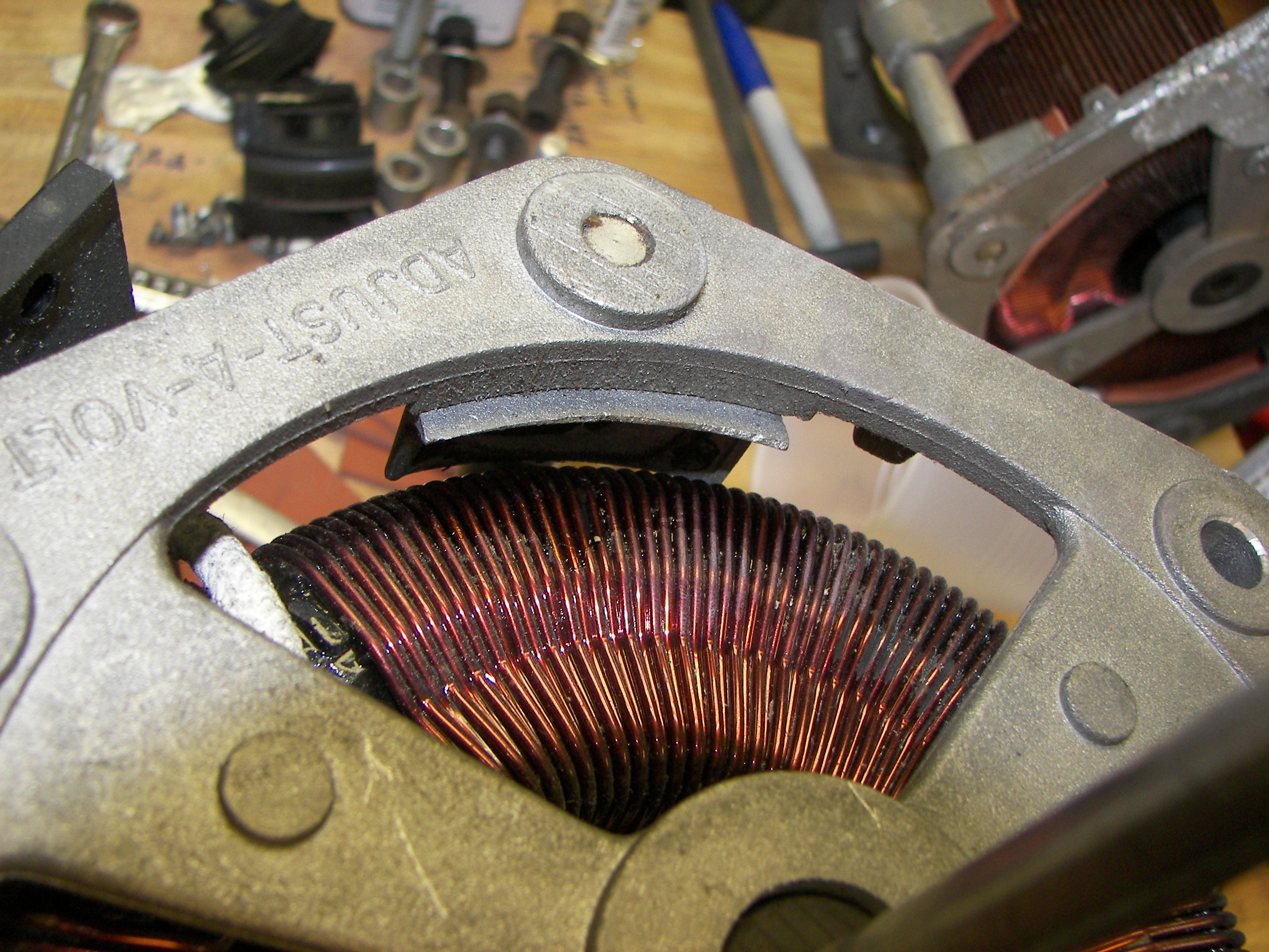
This is how the insulators should appear.
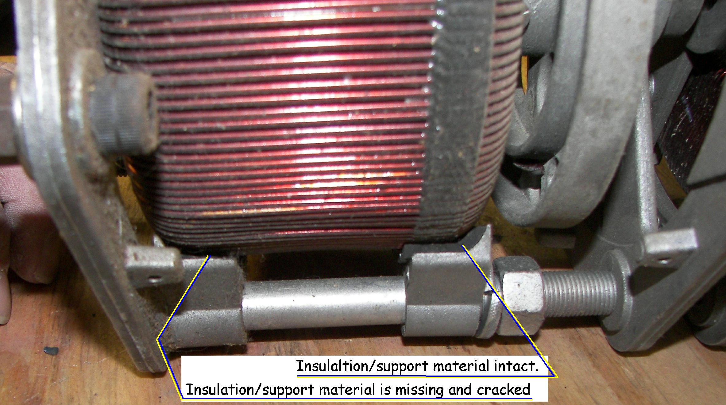
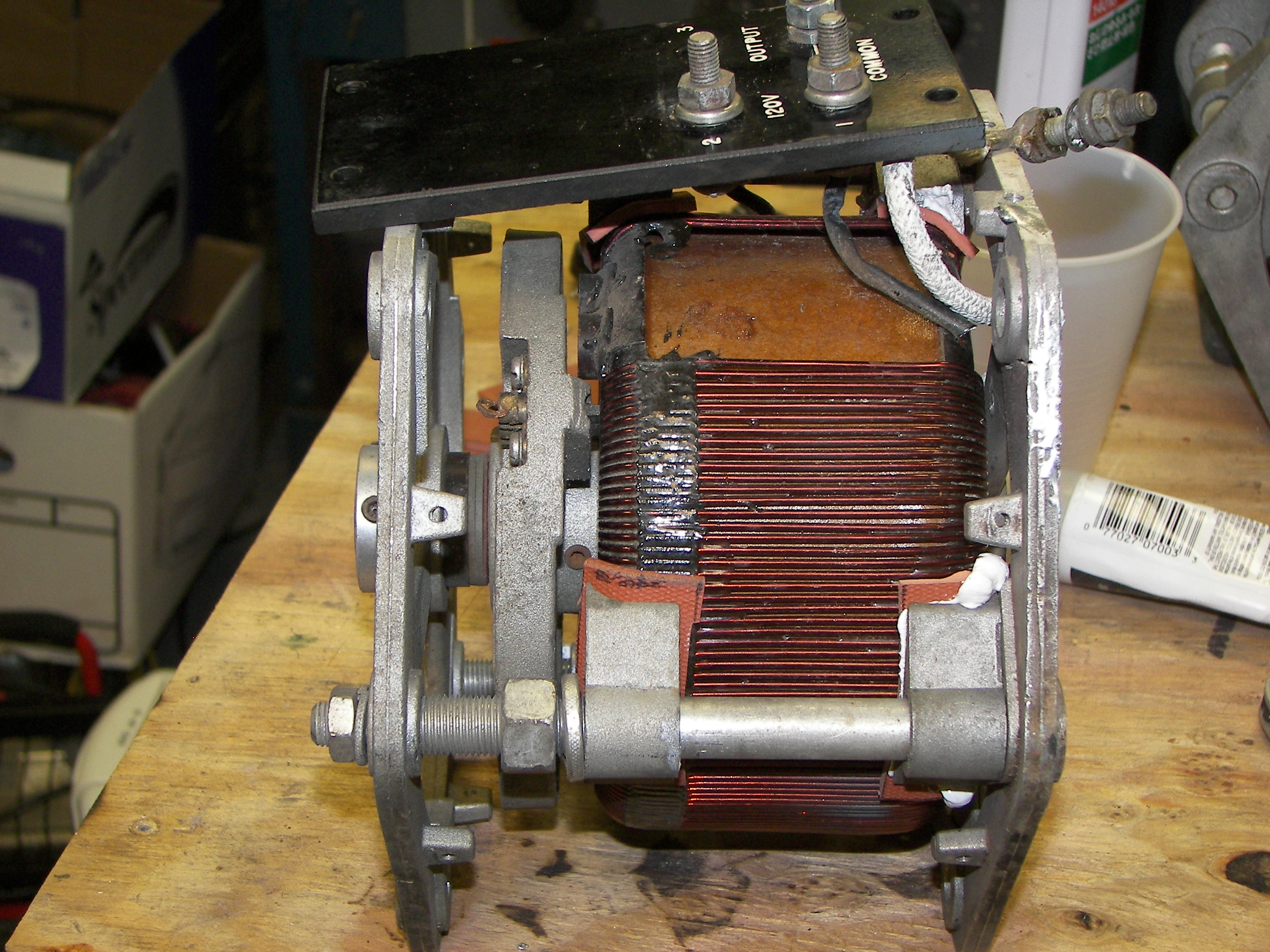
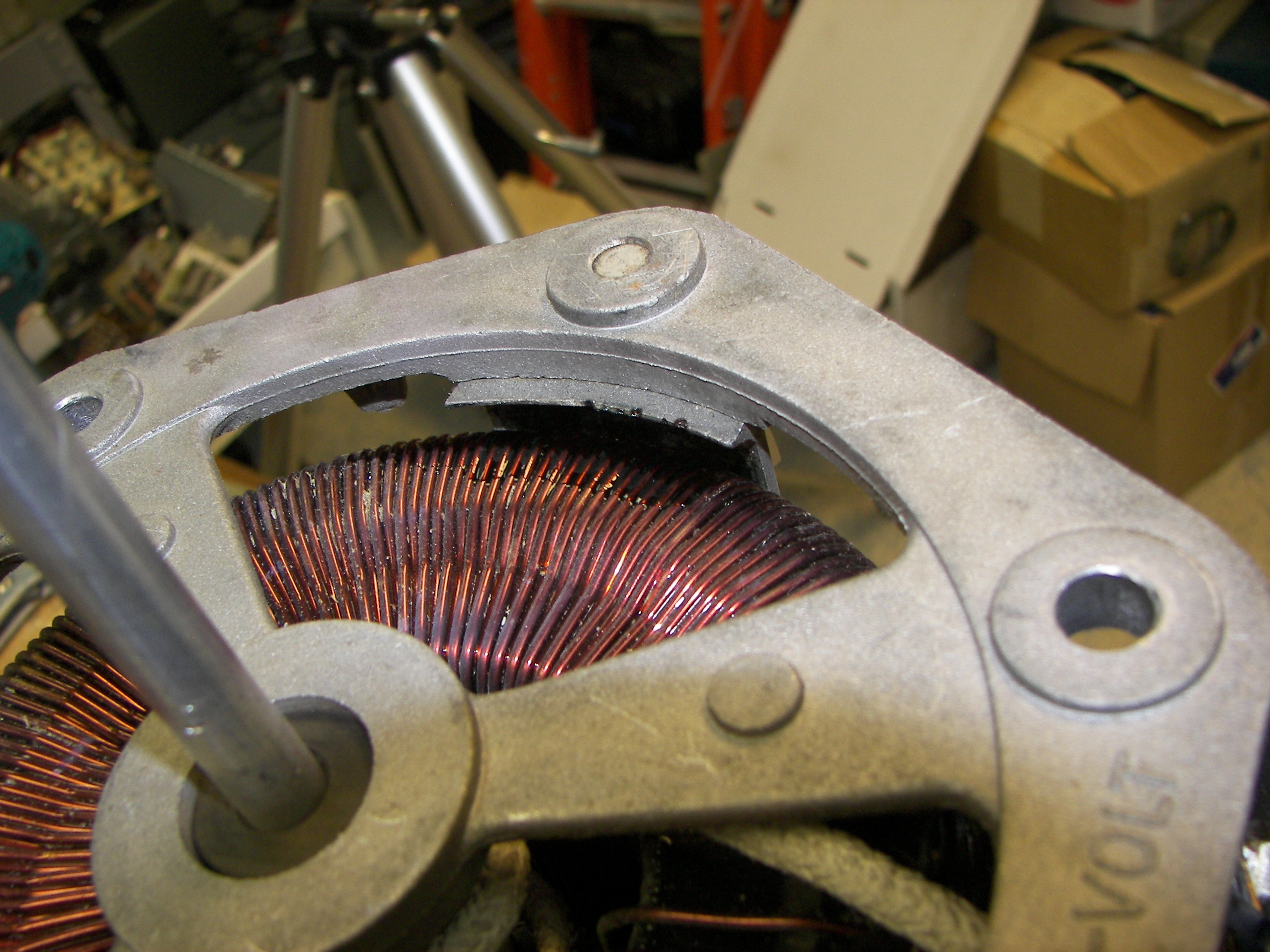
Most of the insulators cracked into many pieces when the unit was dropped. The windings ended up against the metal supports and were slightly damaged, mostly the insulation was nicked. This was repaired with a coat of varnish followed by a thich coat of "three-bond", a plastic goop used for setting screws.
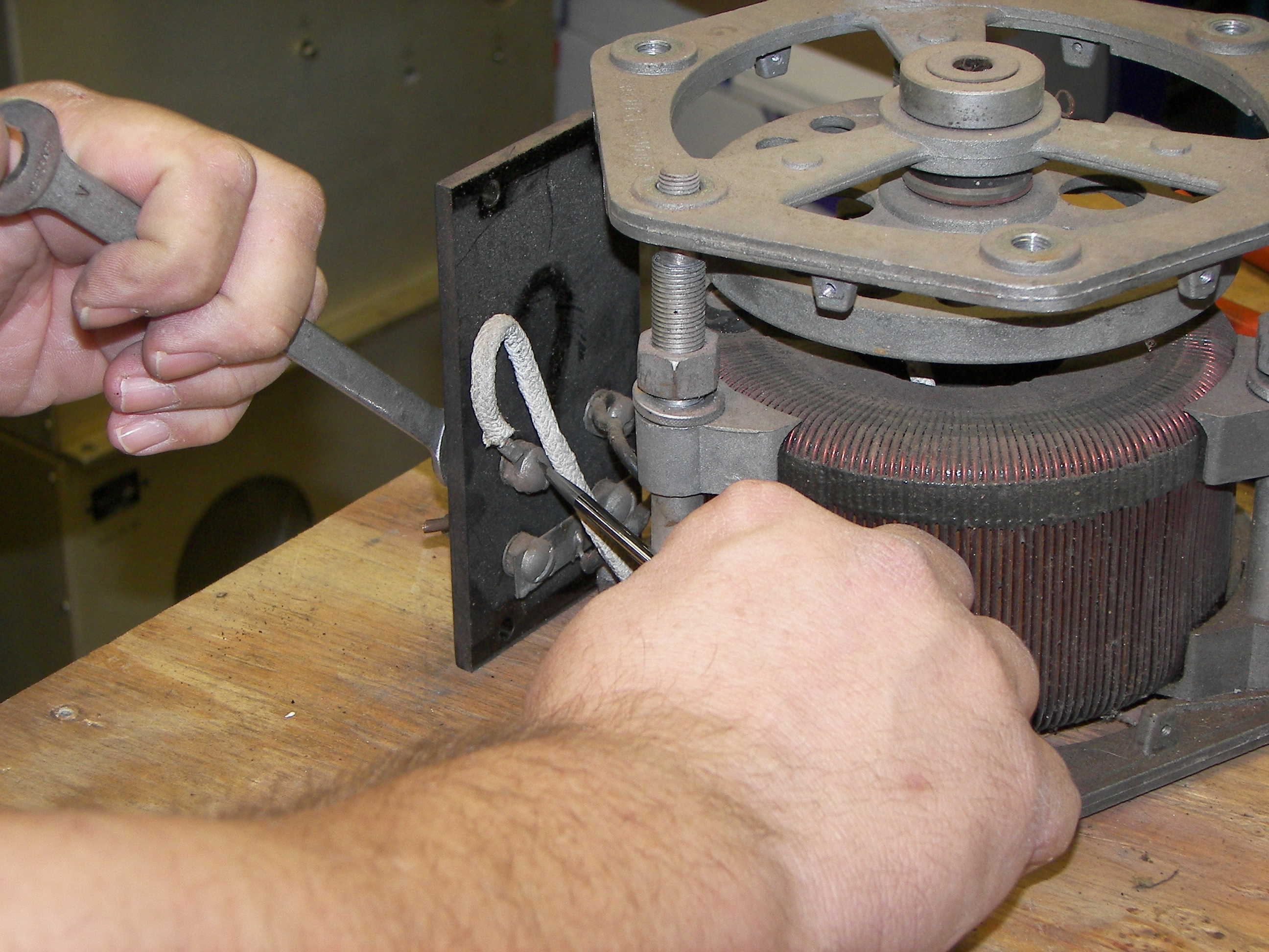
To begin the repair, the front and rear sections must be separated and the rear section disassembled. A hexk key loosens the two set-screws connecting the rear unit drive hib from the operating shaft.
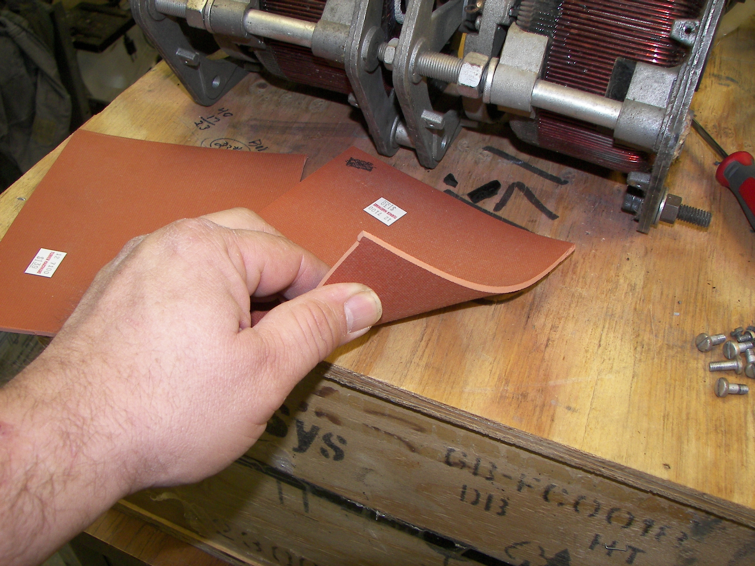
Replacement insulators are not available. A hard and realtively stiff synthetic rubber material with a temperature rating of 200 degrees F was chosen. It is flexible enough to bend under pressure in order to conform to the clamps but hard enough to not be pierced by the clamp edges. 1"x2"x0.25" strips were cut to take the place of the curved insulators. Because the surviving insulators do not compress as much as the synthetic rubber material, all will be replaced by the new material in order to provide symmetry for core re-mounting.
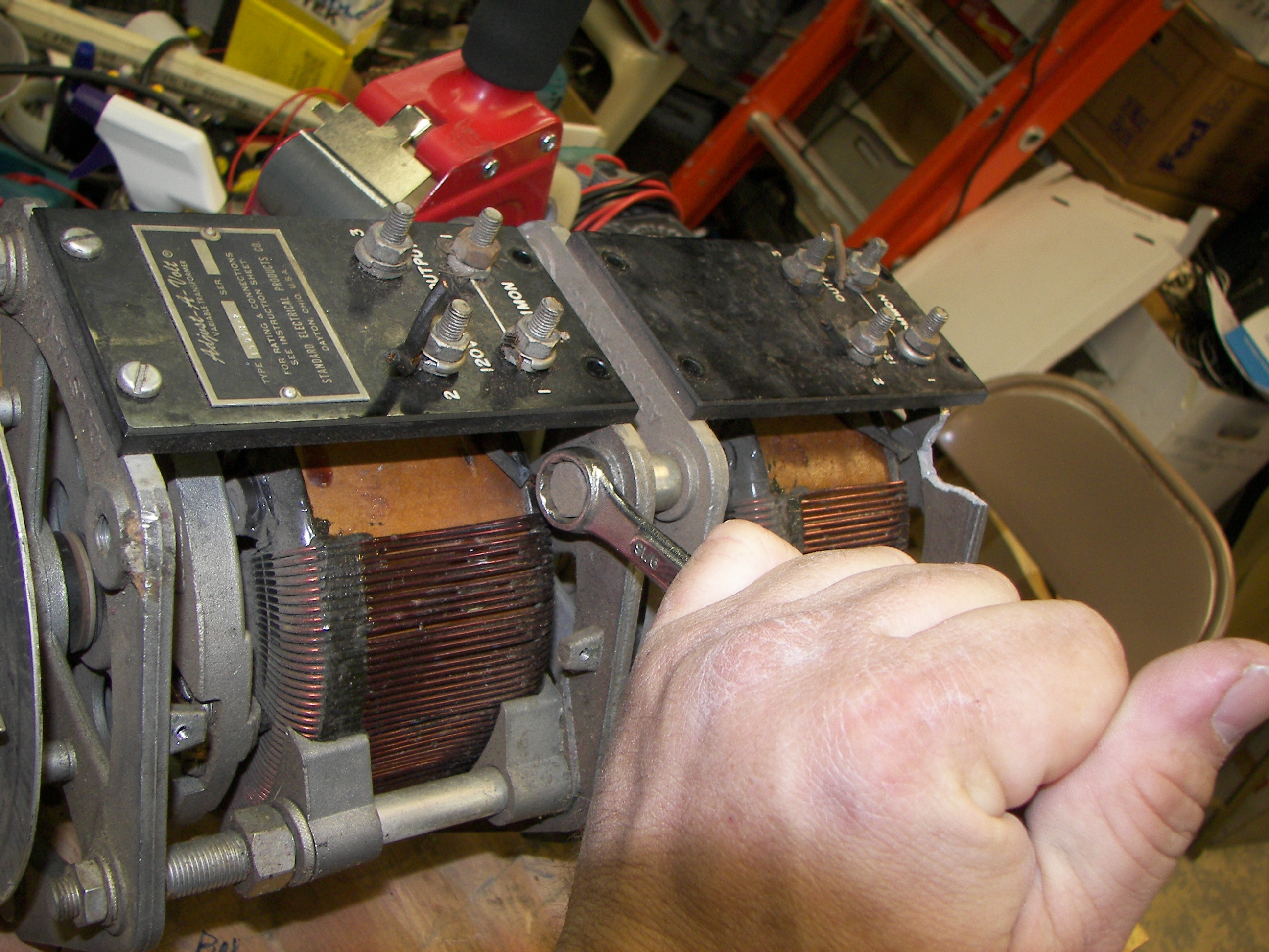
The two sections are separated by removing three large bolts.
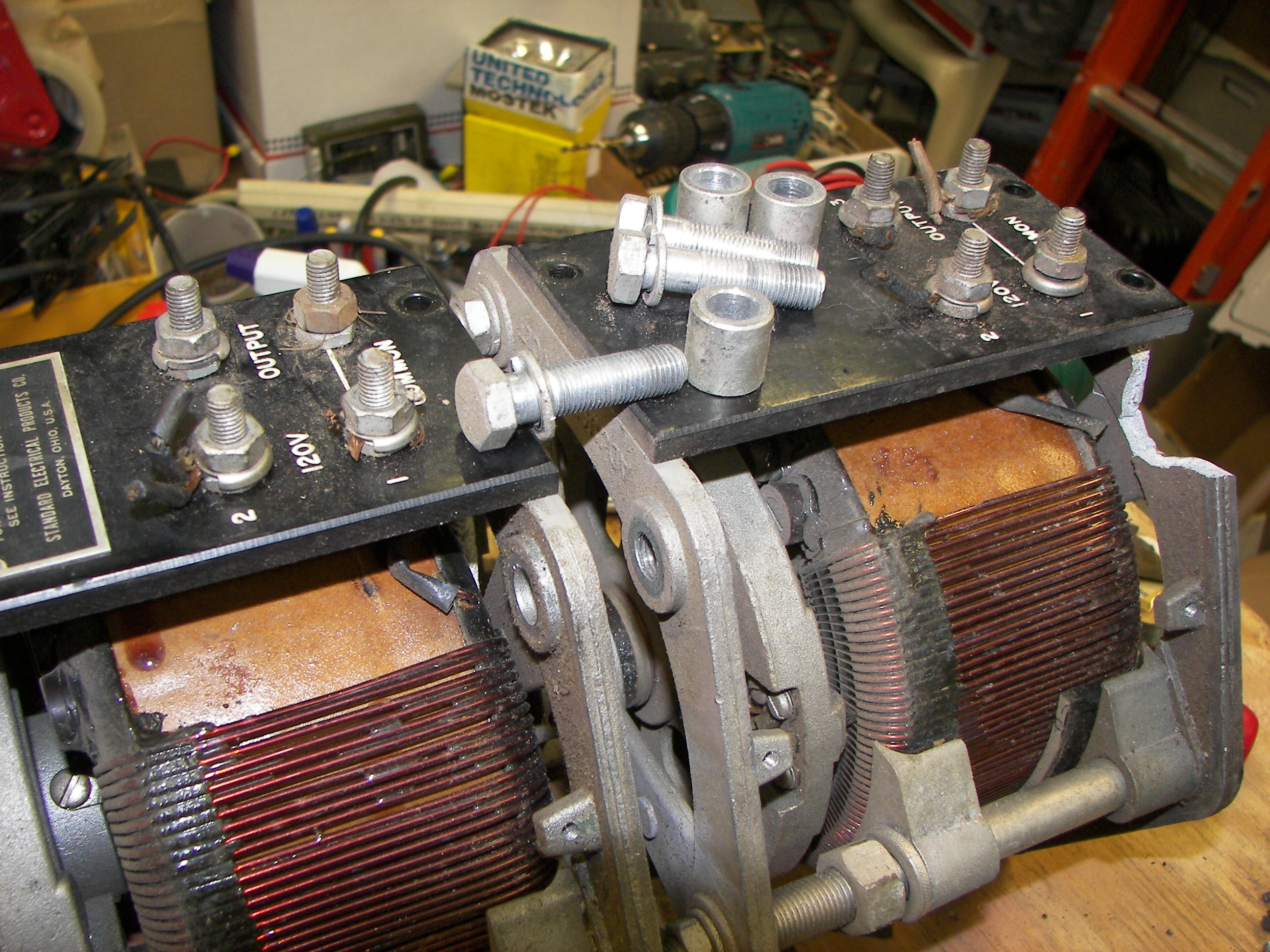
The bolts are removed.
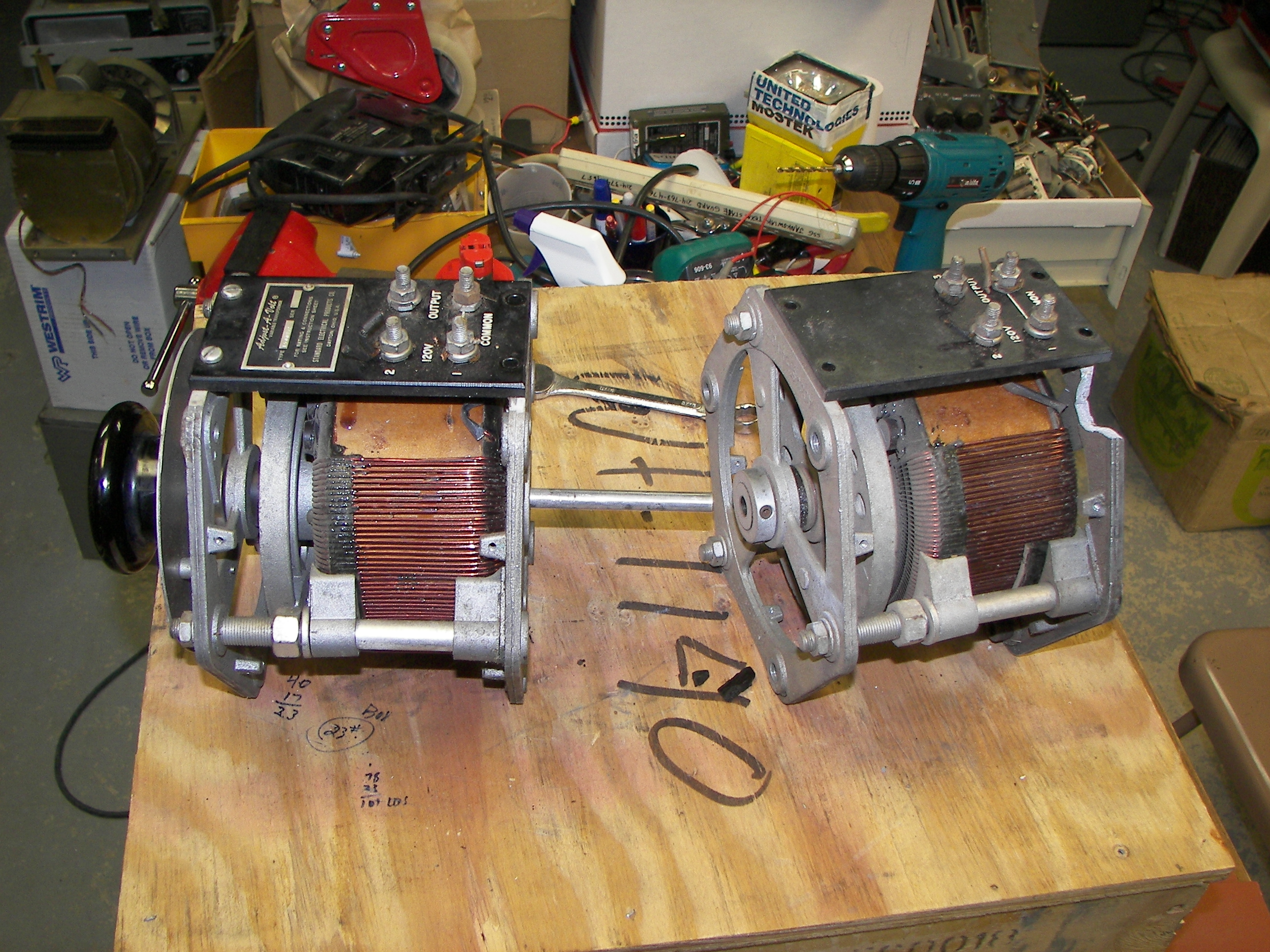
The sections are separated.
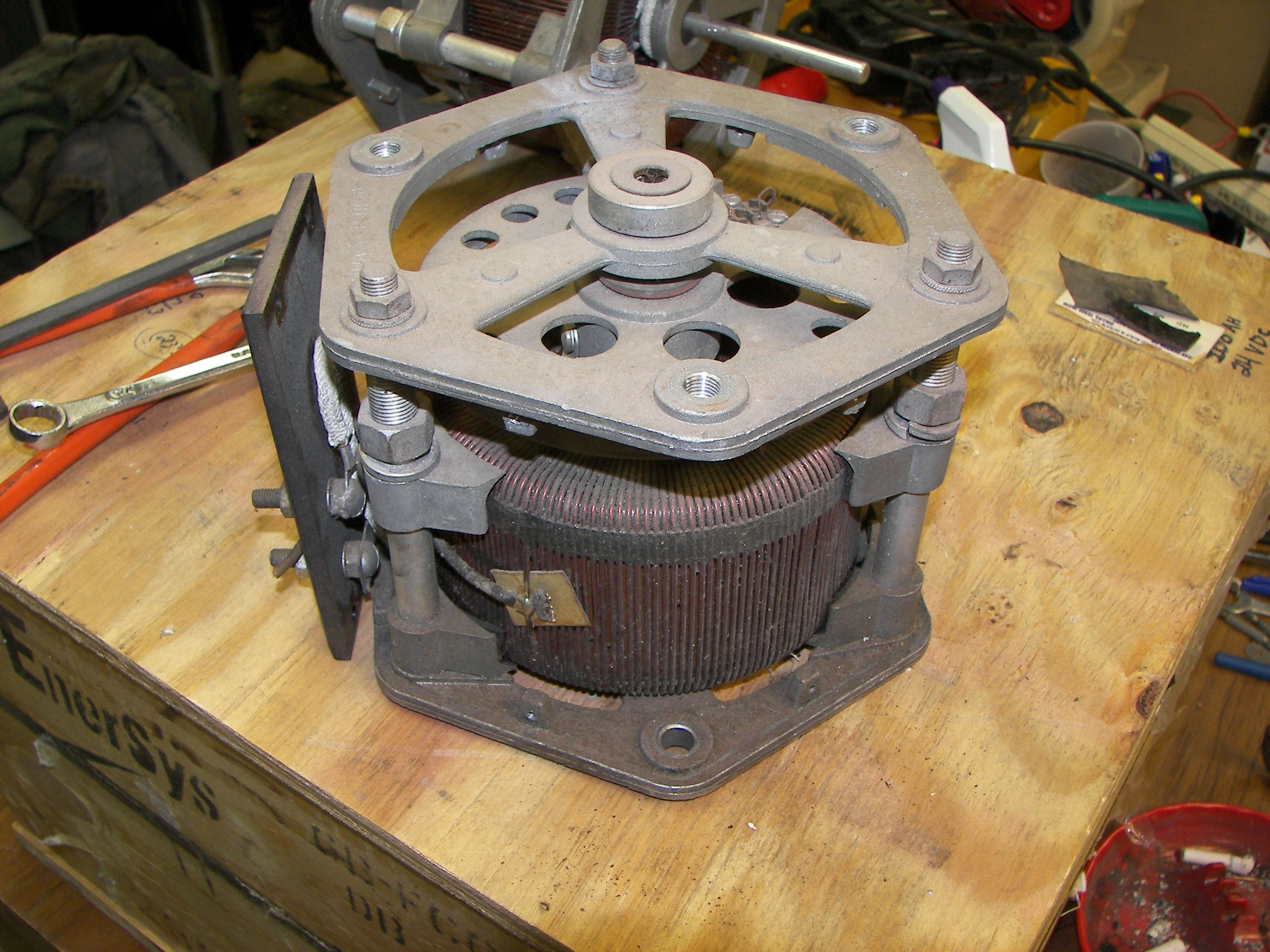
The rear section is ready for disassembly.

The front support nuts are removed.
The large white wire passes through the core center and connects the brush carrier to the terminal block. It is removed from the terminal block.
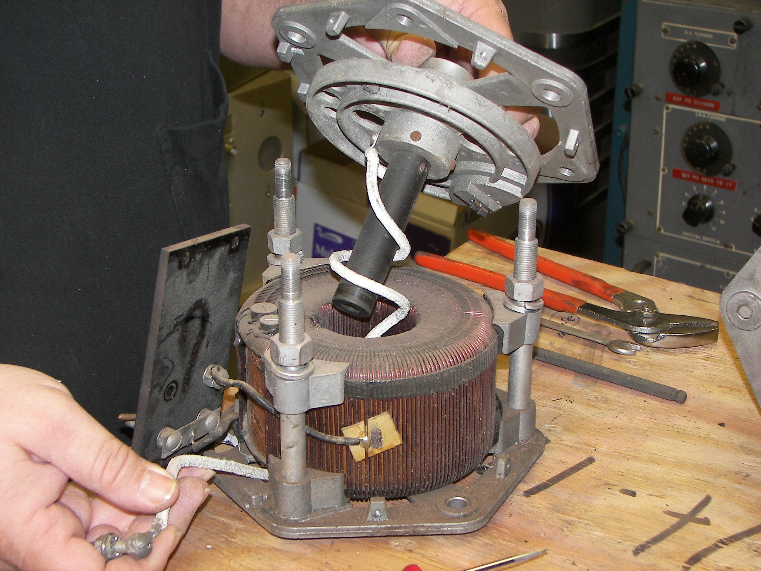
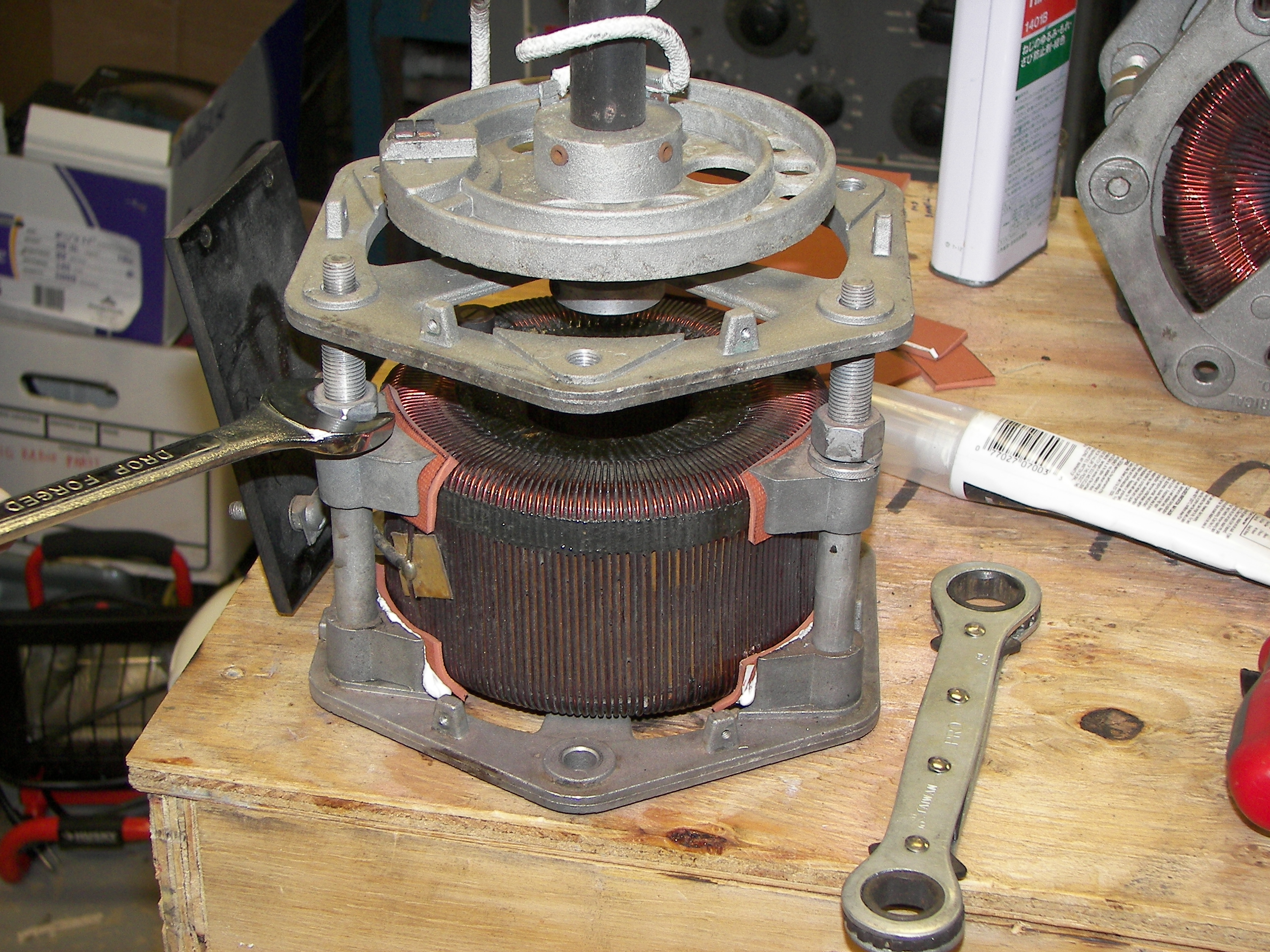
The front plate and brush carrier and axle assembly is removed with care.
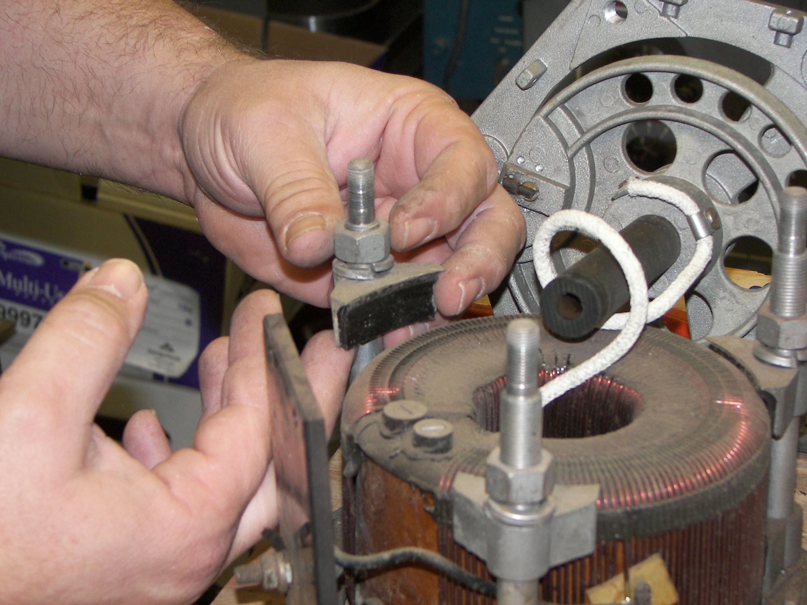
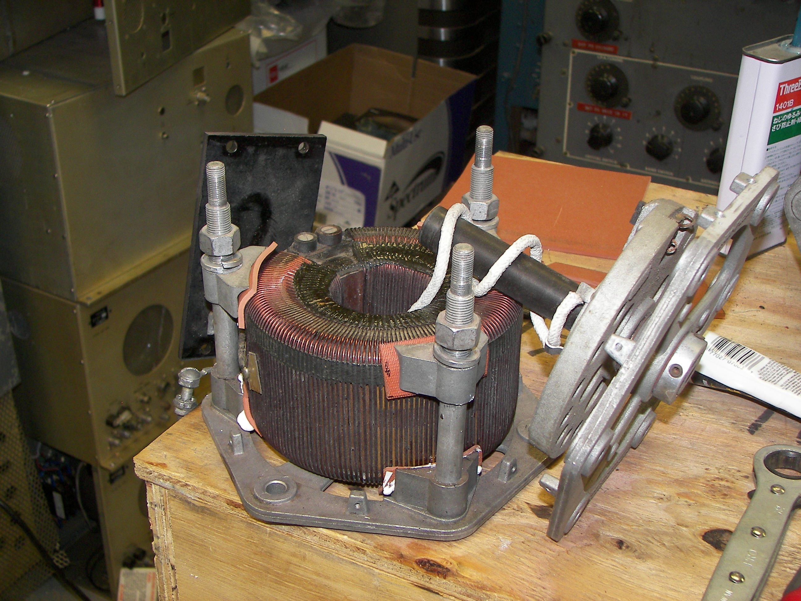
The top core clamp retaining nuts are looseded and the clamps are moved out of the way of the core. Note the brush wire is wrapped twice around the axle. The brish carrier position is at "0" volts. When the voltage is increased, the wire unwraps.This must be noted, no matter the arrangement, in order to put it back together the correct way.
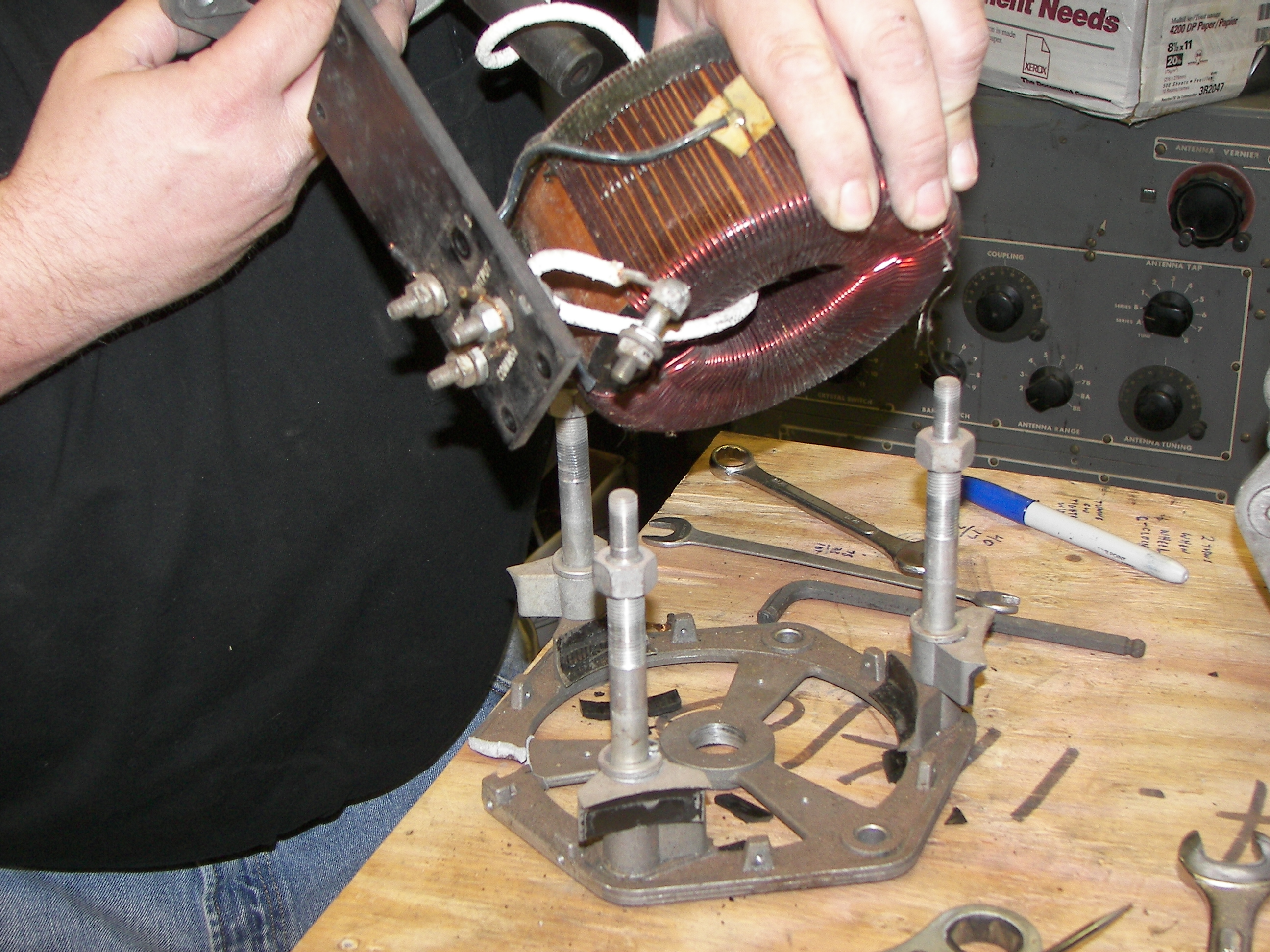
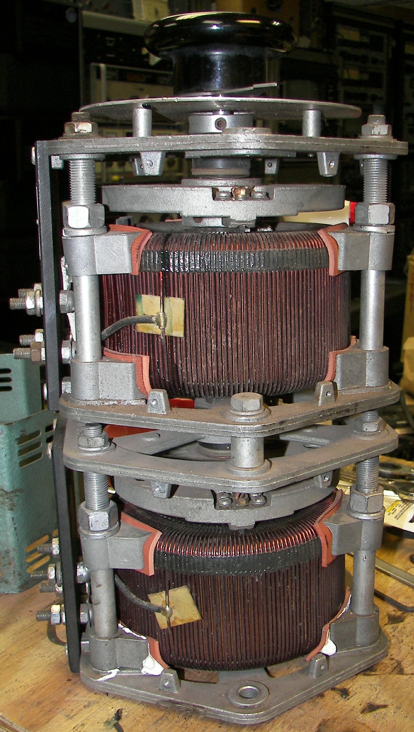
The core is carefully lifted out along with the end assembly. Once the core is clear of the frame, the brush wire will come out through the center of the core.
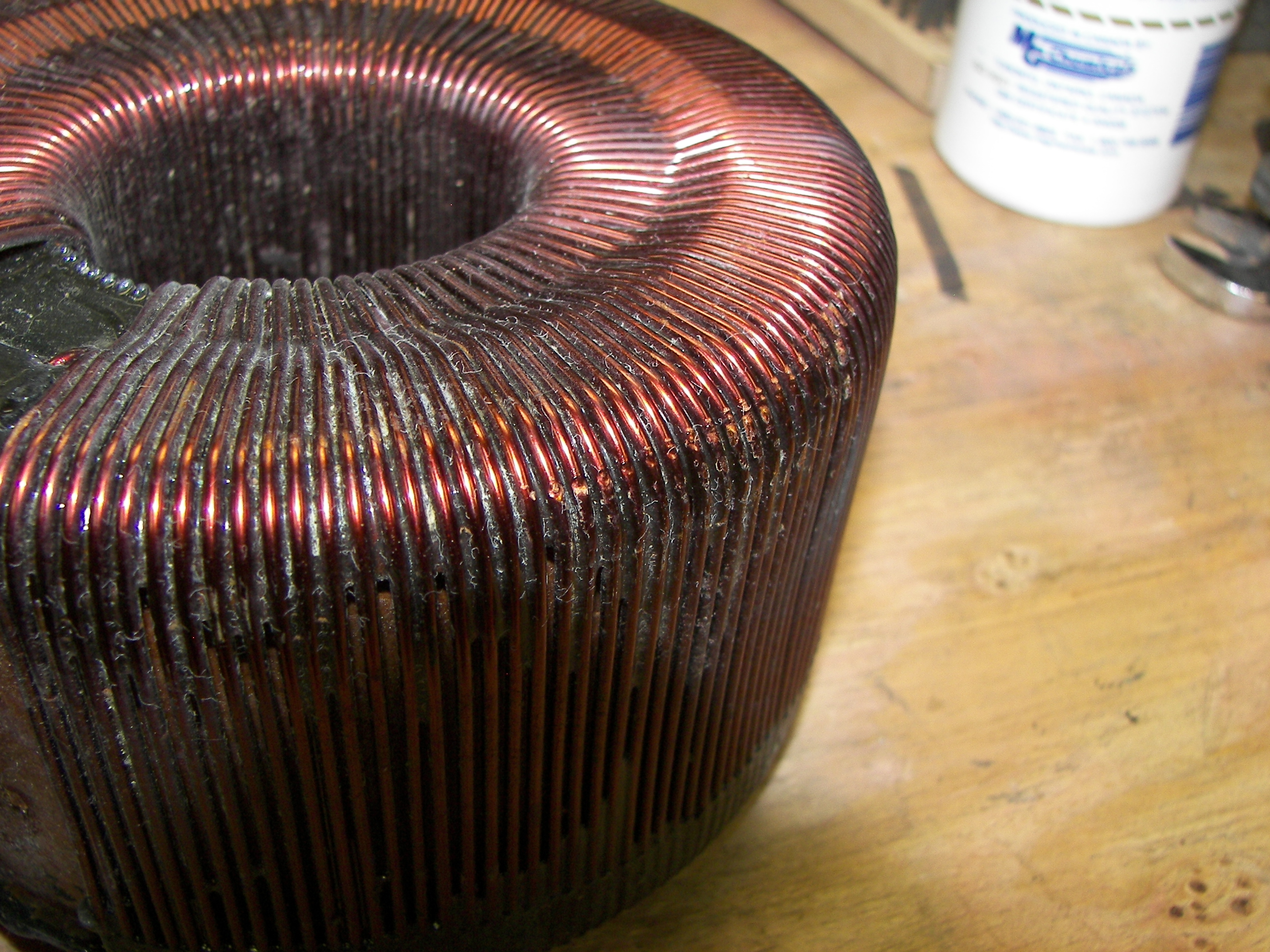
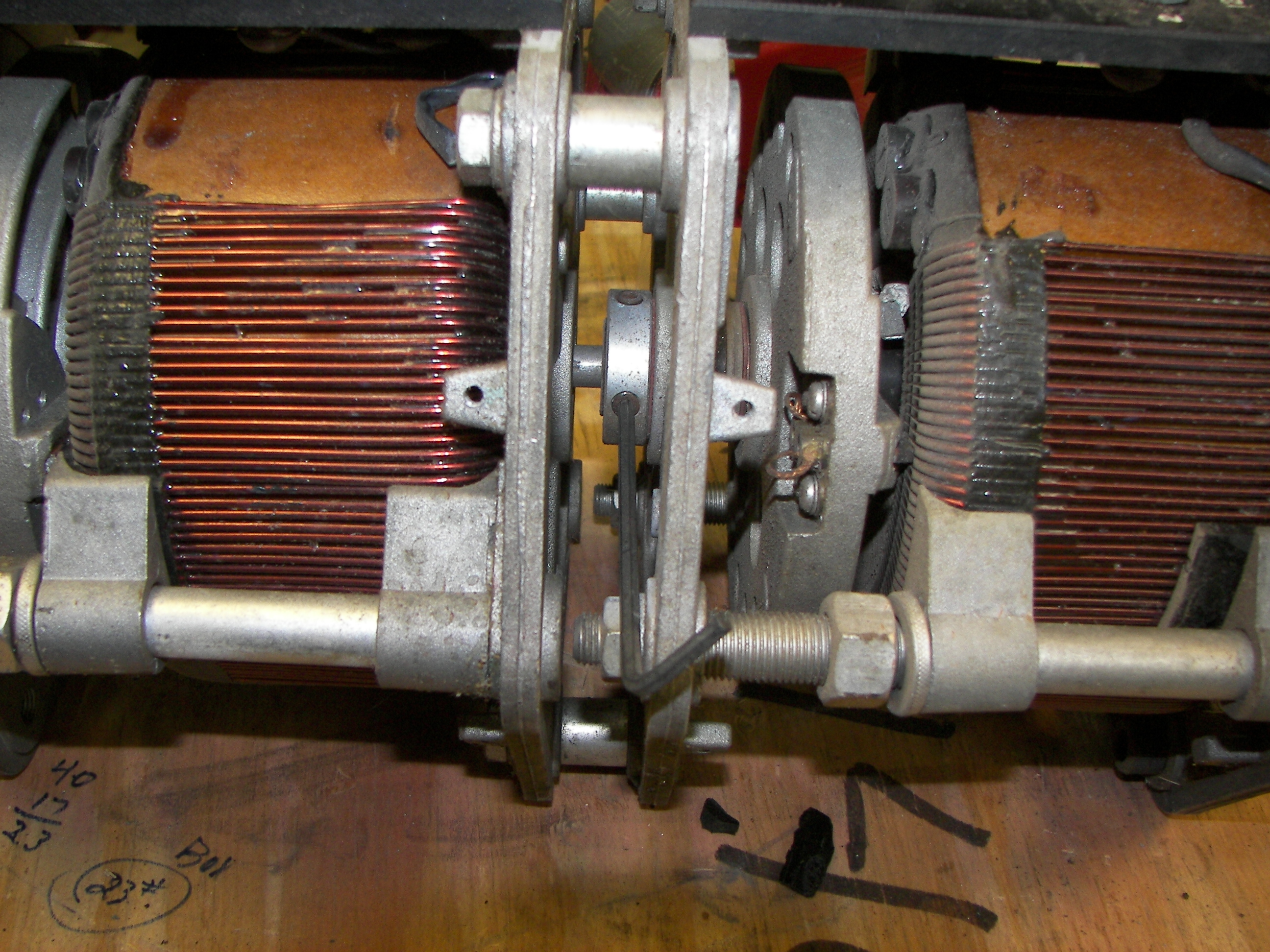
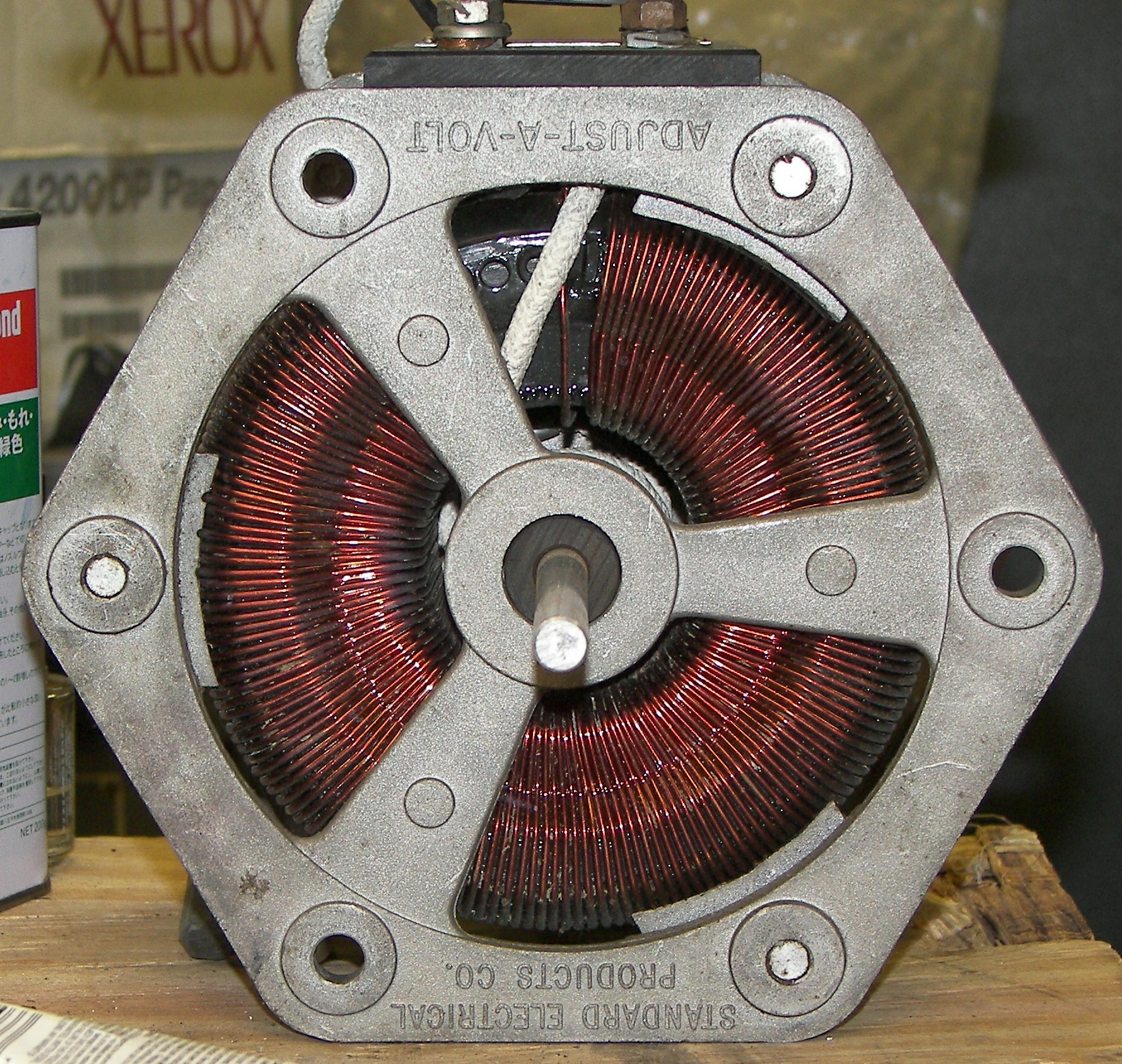
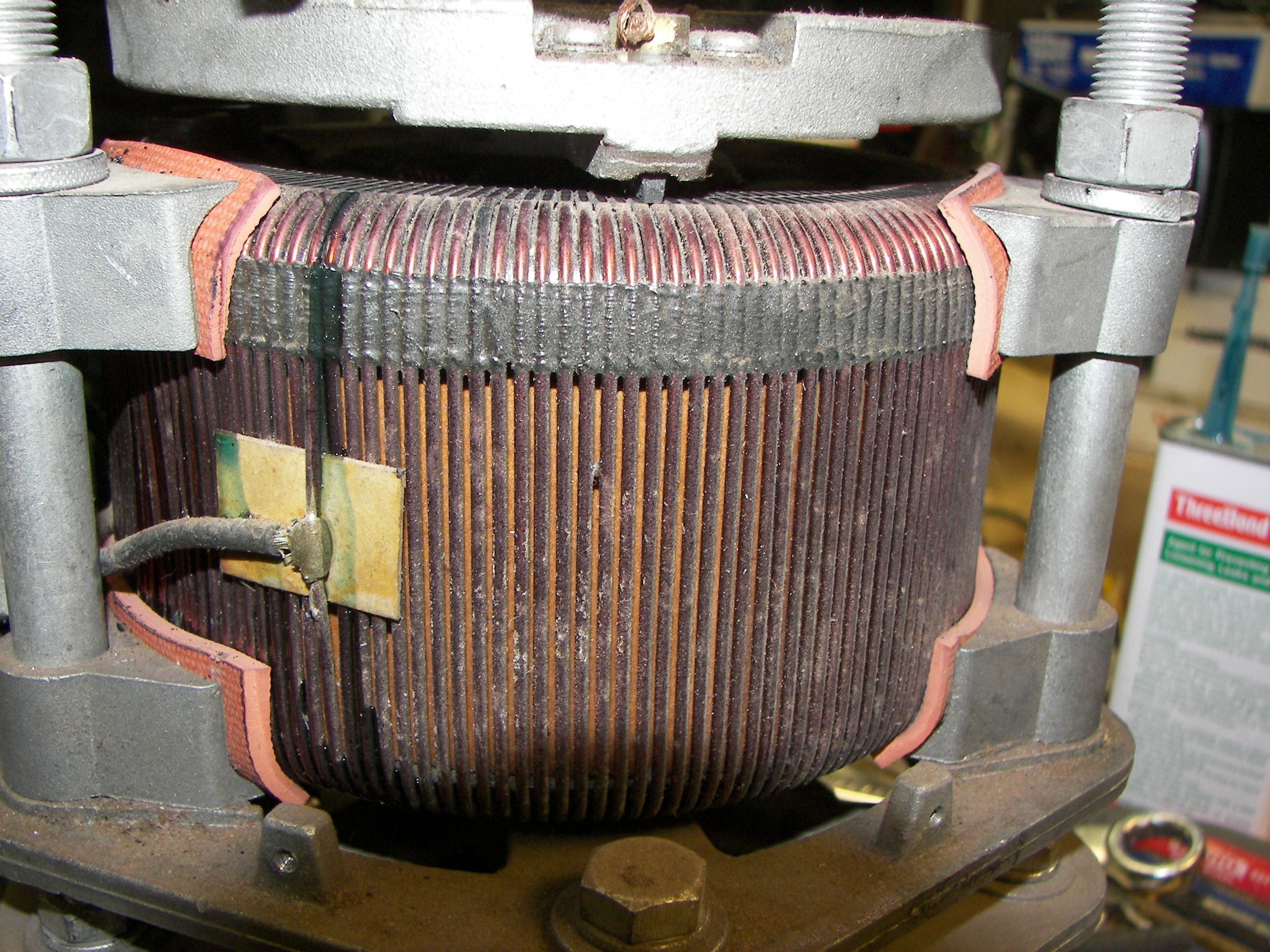
Minor damage can be seen to the windings.
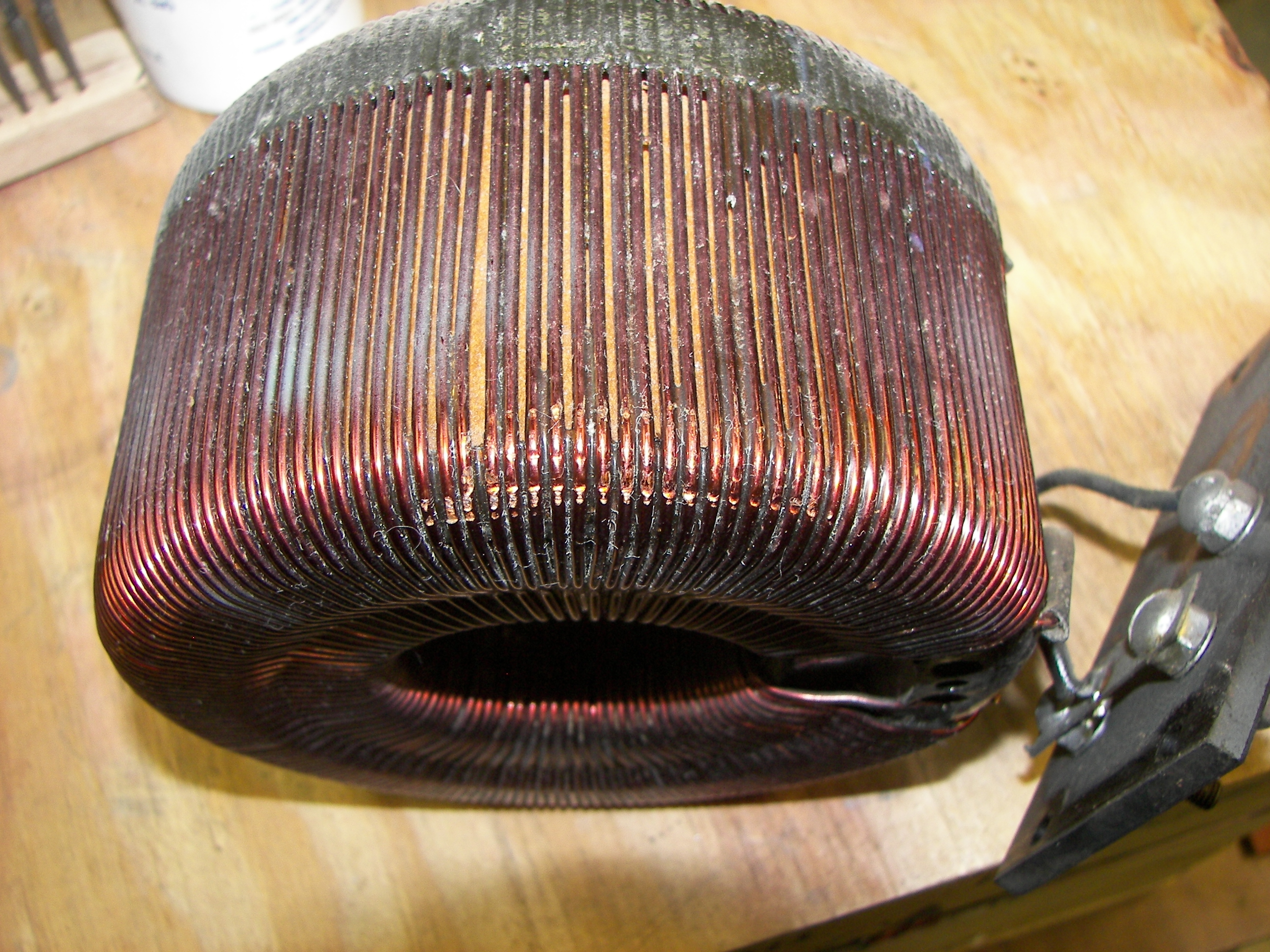
Minor damage can be seen to the windings.

It's filthy as well. A good towel-cleaning with some "409" followed by a circuit board degreaser did the job. The coil's contact areas were cleaned with a stiff brush and contact cleaner.
Time to fix the rear plate.

In the end, smaller clamps were used because this large one kept slipping off. The frame was 'welded' with "alumi-nu", a rod of alloy that melts at a lower termperature than aluminum and bonds to it like solder to copper, yet is harder than aluminum.
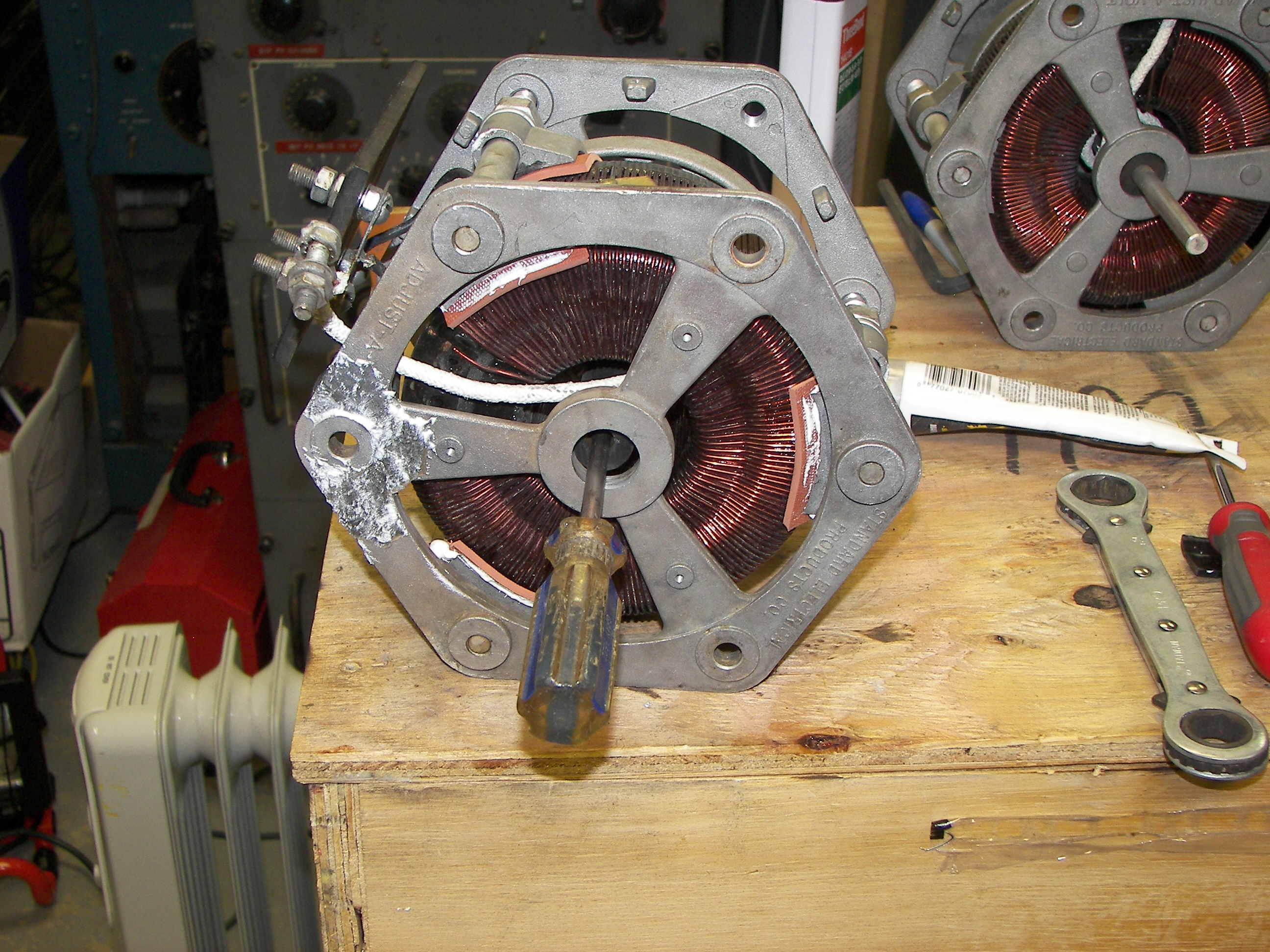
A moment was taken to check the indexing of the front core vs. the frame, so that the rear could be put back the same way. They are the same alignment in this unit and in most multiple units.
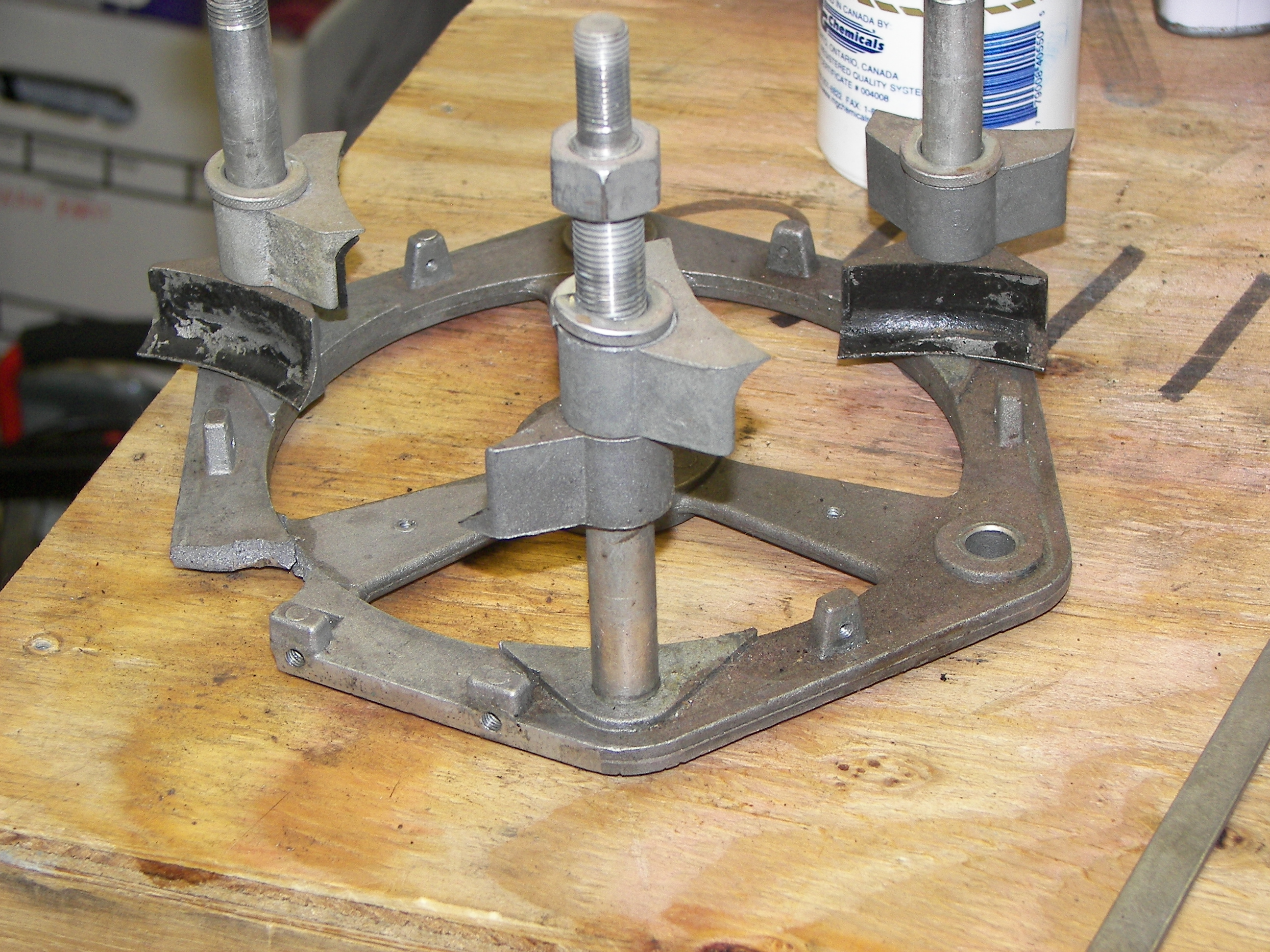
The insulating material was put in place. The lower pieces were held in place with some tacky silicon adhesive while the core was seated. The upper (front) insulators and clamps were put pack, but not tightened. It was also checked that the brush wire would be able to pass between the core and frame for later reassembly.
Putting the front plate on temporarily keeps the three support bolts straight while some tension is put on the assembly. This was done to check the fit of the insulation and the assembly to make sure the material was going to work. It was put in upside down in order to have the most visibility of the mountings.
Once I was satisfied, the upper (front) clamp bolts were loosened, the front plate turned the right way, and the assembly put back together. The axle didn't want to align easily with the hole in the plate, so a screwdriver was used to line it up. The aluminum repair can be seen.
The unit basically together, ready for the front plate bolts to be tighened.

Now the core clamp nuts can be tighened and should be done so equally. The compression washers may not need to be completely compressed, since the insulating material is different. use care to tighten them evenly and firmly, observing the material for deformation of thickness, which should be avoided. Note that the insulation goes beyond the front edge of the front core clamp (same at the rear clamp, but it extends further to the rear instead). At this stage it may interfere with the rotation of the brush carrier, but as the clamp is tightened, it will snug down out of the way.
The front section was repaired in-frame. A bit challenging, but not impossible.
A good shot of the new insulation and how it is is positioned.
Good as new! The covers will be put on, and the unit can be put to use. A test following the repair showed perfect operation. I think Standard Electrical Products Co. would be proud of me!