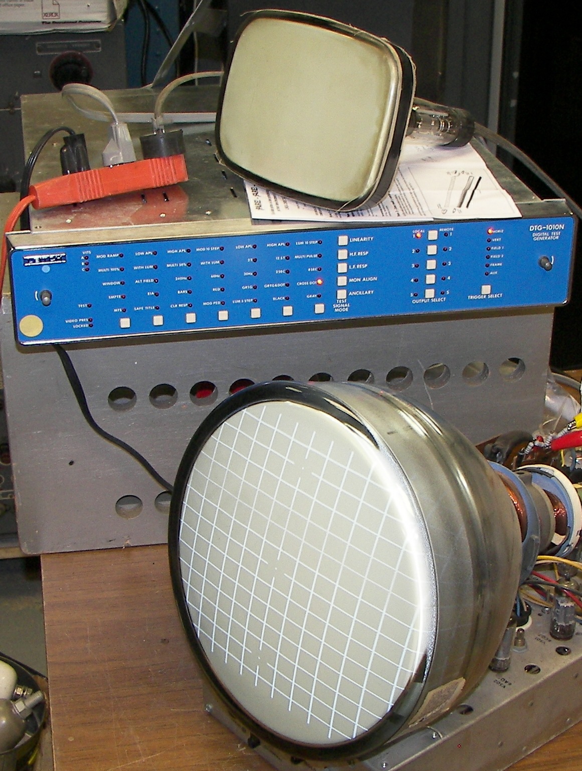
The monitor chassis is an RCA TM-9AN video monitor, an ancient 8" black and white type running 16KV accelerating voltage, with very high brightness and resolution used in TV studios of the 1950's. The actual manufacturer is Conrac and their model is CNA-8. The original CRT is an 8MP4 or 8NP4. There do not seem to be any collectors for these, so at least I am keeping them from the landfill. The 10" tube I am using is a 10SP4 TV set tube. I have plenty of the NOS. In case anyone needs one or more, please refer to the magnetosphere. Assuming I can get the other chassis' up and running, I intend to later do the same with a 10SP7, 10UP14, 10VP15, and 10VP47, all of which have unusual phosphors designed for RADAR and should prove interesting. This one is the first one, for proof and debug. |
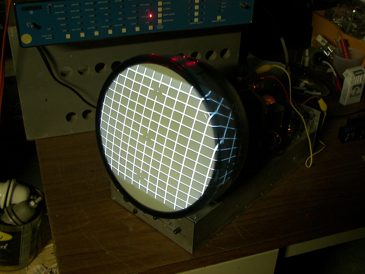
Because the original 8" rectangular CRT has a 110 degree deflection angle and the desired 10" round CRT has a 65 degree angle, significant overscan exists in the horizontal direction as can be seen by observation in a darkened room. (The chassis also has some vertical linearity issues that need to be resolved later) |
Front view of the original scan. |
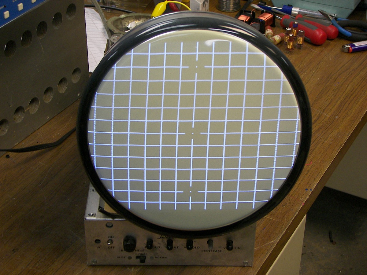
Front view with 5mH non-saturating inductance placed in series with the horizontal yoke winding. The scan is reduced to a usable size, but there are nonlinearities and parasitic oscillations introduced because the added inductance has upset the resonant frequency of the horizontal circuit. The next step in the investigation will be to see if there is a lower voltage tap on the flyback transformer to which the yoke can be connected in order to reduce its current. The best way to do it would be to obtain a 50 to 65 degree yoke, but yokes with that angle are in rather short supply today. Furthermore, the replacement yoke would need to have similar inductance and resistance characteristics in order to make a good impedance match and where the horizontal winding is concerned, proper tuning. |
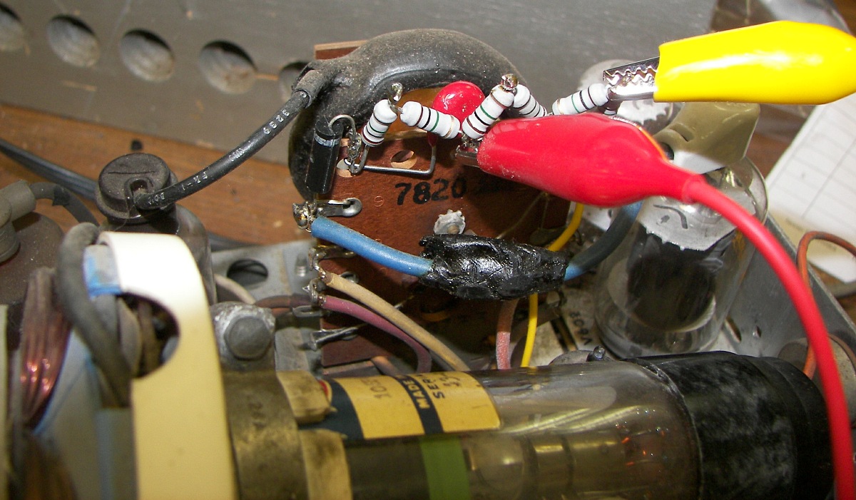
The original CRT required only 200-600 volts DC for focusing. The NOS 10SP4, of which I have plenty, BTW, requires 1600-2500VDC. There is no place on this chassis to obtain the voltage. Boost is 600V. The solution was to connect a 15KV rectifier attached to the horizontal output tube's anode and use it to charge a 500pF capacitor. A voltage divider made of six 1-megohm 1-watt resistors serves as a voltage divider and the entire thing makes about 4500V. One tap at about 3000V (unloaded) goes to the focus electrode and one at about 800V goes to the existing focus control's wiper, returned to a range from boost to ground. This brings the focus voltage in range. This was a fun little part of the project. |
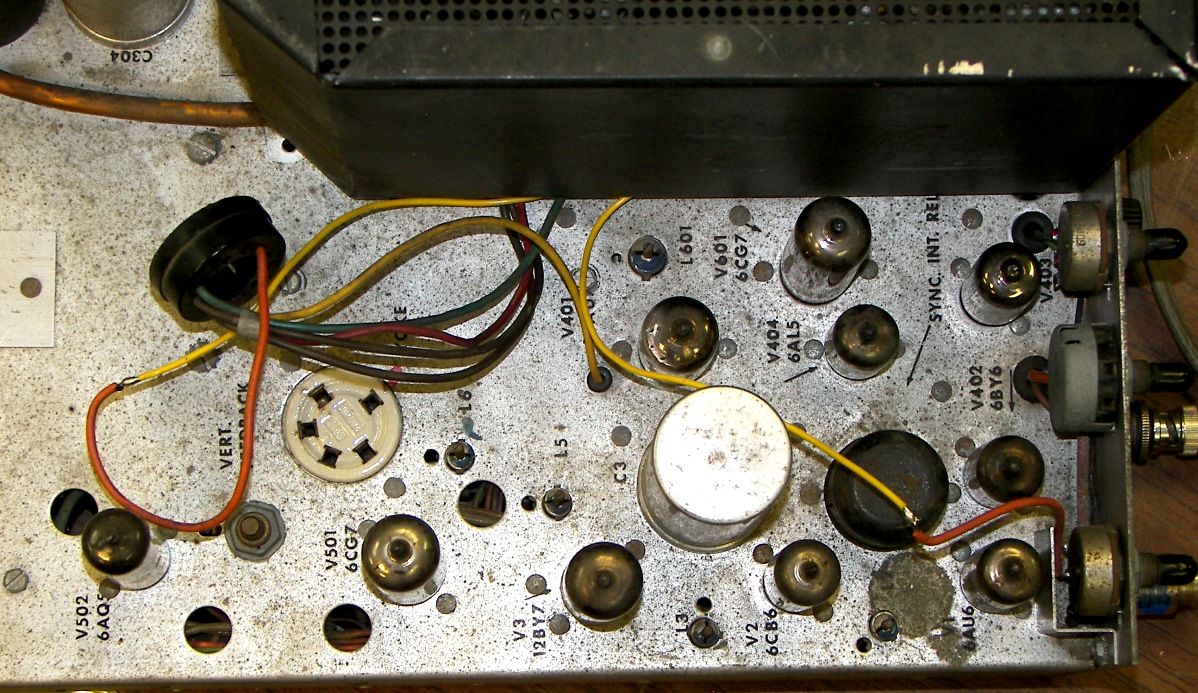
Just a picture of the vacuum tube layout, except the horizontal output, damper rectifier, and high voltage rectifer. They are in the black box. |