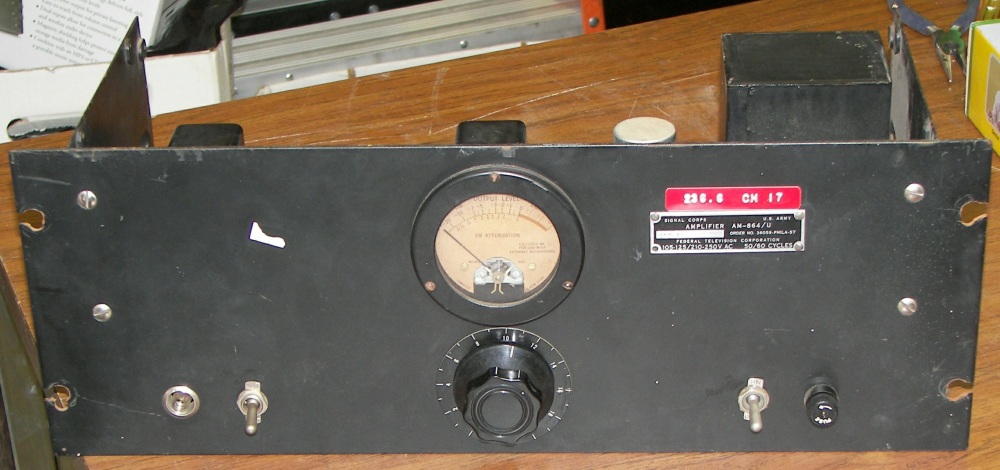
Federal TV corp. AM-864/U audio compressor
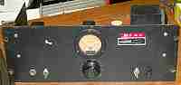
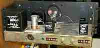
Front panel. From left to right: Pilot lamp (missing the jewel lens in this image), meter switch selecting output or degree of compression, meter and input attenuator knob, power switch, and fuseholder.
|
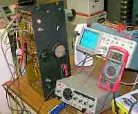
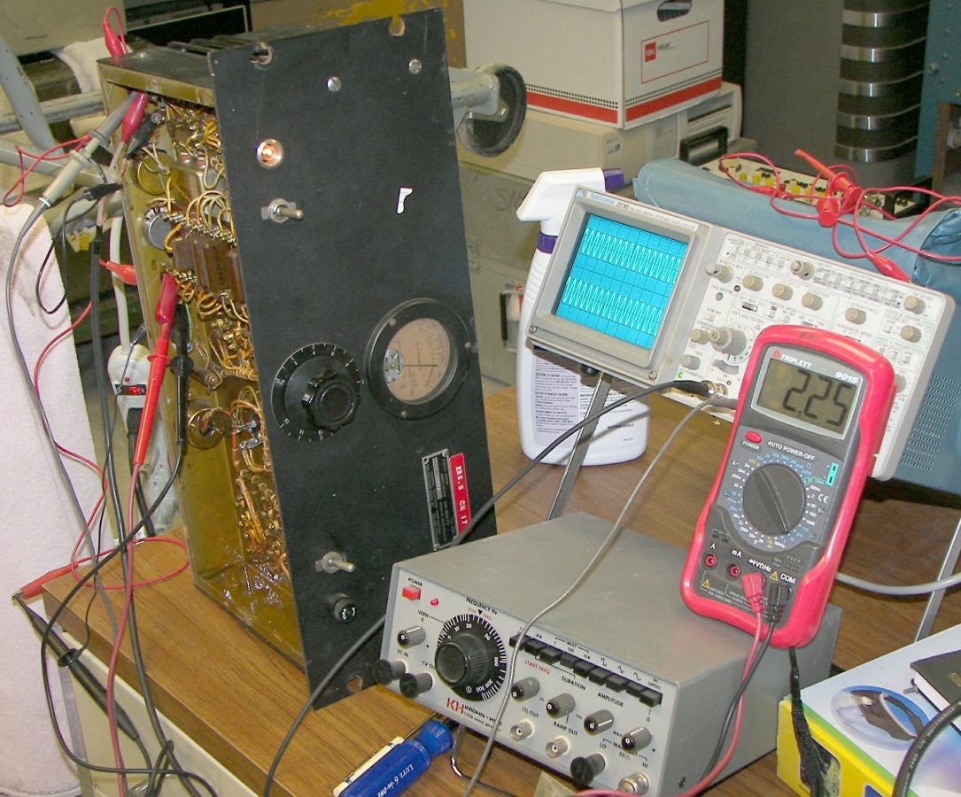
Unit under test, working well with. Two tubes were replaced and the controls were cleaned. The unit probably should have capacitors C2, C3, C5, and C6 replaced on age/general principles.
|
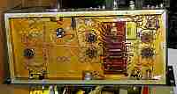
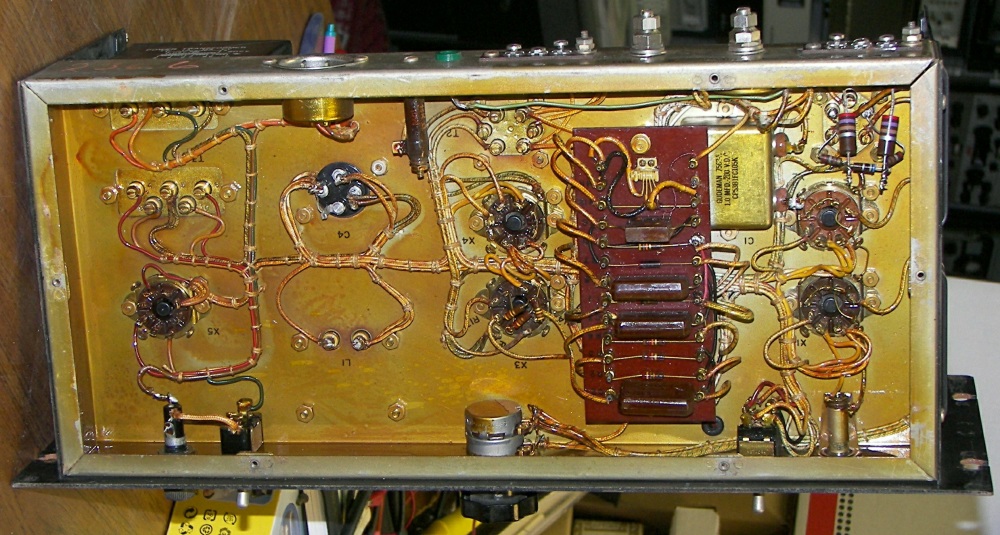
Underside of unit showing of tropicalizing coating on all components.
|
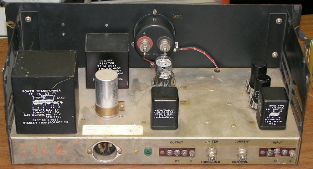
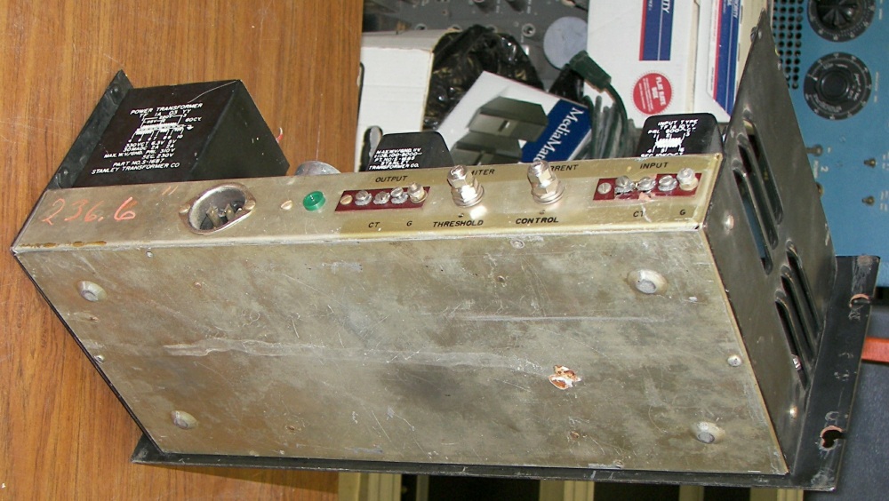
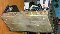
Rear view. The chassis cover is missing on this unit. It is merely a black steel cover for the top and rear, so one can be fabricated easily.
|
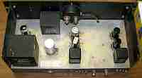
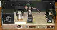
Top view
|
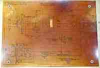
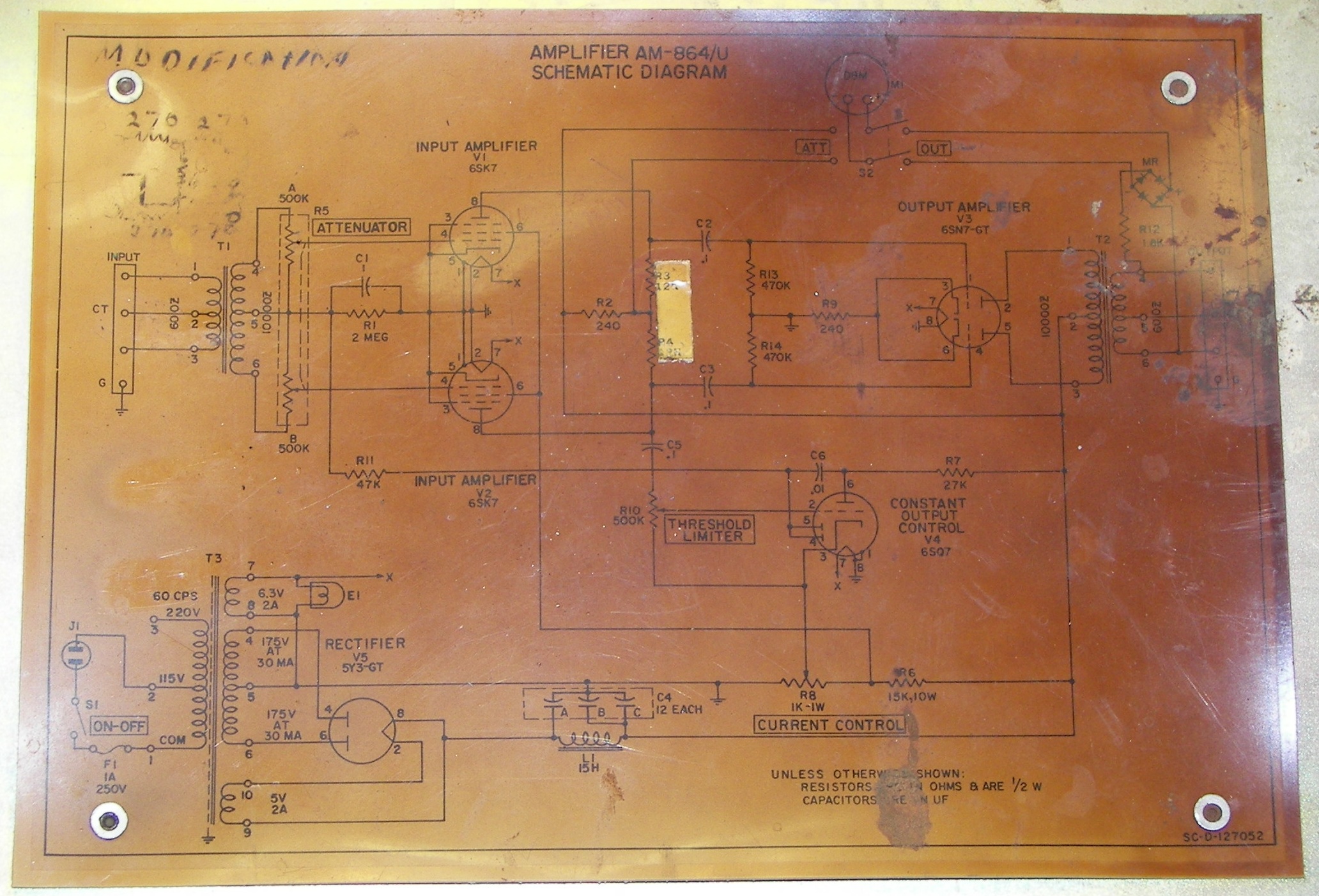
Schematic is affixed to the inside of the bottom cover. Although it looks like it has suffered from heat, it is merely old and the lamiation has failed. Some examples of the schematic have survived better but it is no indication of problems if not.
|
Bottom cover in place.
|
Rear view. Of note, the input terminal strip is broken. It is not an uncommon type and can be substituted. Note when using the compressor, that at least one of the input terminals should be grounded in ordr to avoid parasitic oscillations. The input and output of the unit are completely isolated from ground allowing greatest flexibility, but a ground return is reccommended.
|
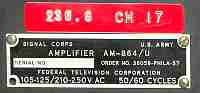
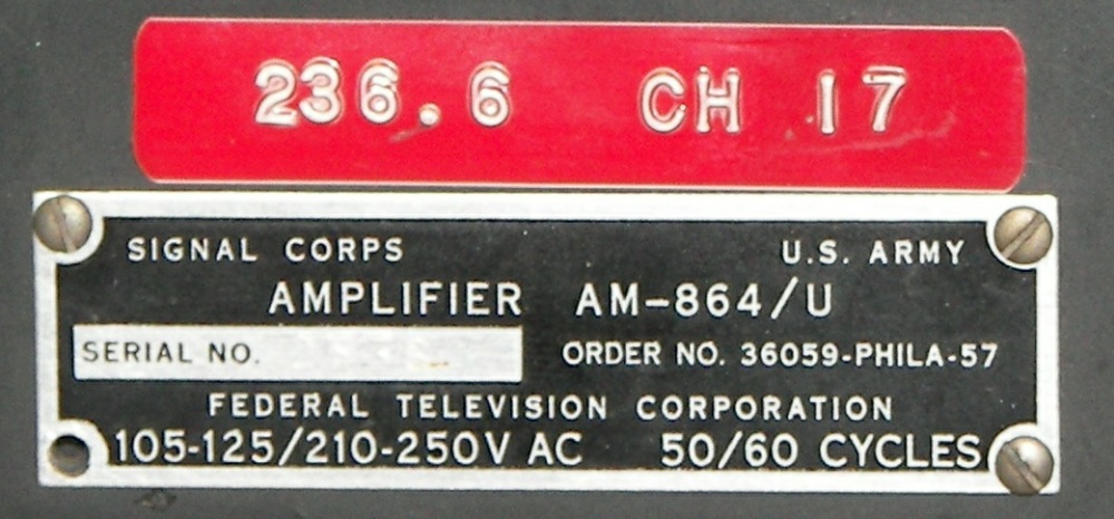
Data Plate
|
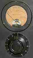
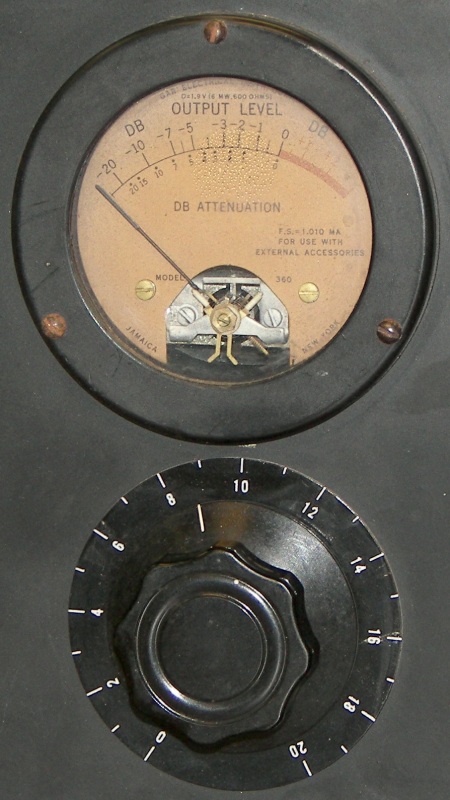
The beautiful meter and attenuator control
|
Operation:
Amplification: Input from the 600 ohm source passes through T1 and is transformed to a balanced signal. The audio signal remains balanced throughout the unit. For simplicity, the 'top' half of the balanced audio path is described. the 'bottom' half is exactly alike except for the signal polarity. R5A the attenuator control divides the signal voltage by an amount determined by the setting of R5. This signal is applied directly to the grid of V1 the 6SK7. (Note: under no-signal conditions, V1 and V2 operate in a zero-bias condition. Therefore the design is such that the screen grid voltages on these tubes is very low.) V1 amplifies the signal and the amplified signal appears at pin 8 the plate connection. From this node the signal passes through coupling capacitor C2 to the grid pin 1 of V3. V3 further amplfies the signal and feeds it to output transformer T2 which then transforms the high impedance of V3's plate circuit to the 600 ohm line output impedance.
Metering: Switch S2 connecta dBm meter M1 to either a selenium metal rectifier connected to the 600 ohm output circuit or to a 240 ohm current shunt R2 in the plate supply circuit of V1 and V2.
When the switch is in the upper position, the meter is connected to the amplifier output. It reads the the output directly calibrated in dBm. In this unit, zero dBm indicated on the meter seems to equate to about 2.45V RMS which is reasonably 10mW into 600 ohms ("old skool").
When the switch is in the lower position, the meter measures the degree of automatic attenuation in dB. This is indicated on the meter face aS "DB ATTENUATION" and is readable in 1dB increments. The normal position of the pointer in this switch position is at the Zero mark on the compression scale (This mark coincides with the zero dB output mark on the "OUTPUT LEVEL" scale). This position of the meter needle indicates a current flow of approximately 10mA total through the plate circuits of V1 and V2 6SK7 input amplifiers, operating in Class A. In the presence of automatic attenuation, the current through V1 and V2 is reduced by the control circuit and the indication on the meter moves downscale indicating increasing levels of attenuation.
Compression: The signal voltage generated at pin 8 of 6SK7 input amplifier V2 is fed through coupling capacitor C5 to threshold limiter setting control R10. R10 divides the voltage from V2 into a voltage suitable for calibration of the signal level at which automatic attenuation should begin to occur as well as the aggressiveness of the attenuation action. The selected portion of the signal voltage is fed to pin 2 the grid of V4 the constand output coltrol tube. V4 amplifies the signal and the amplified signal appears at pin 6 the plate conection, where it is coupled by C6 to pin5 and pin 6 the diode sections of V4. Due to this action, positive half-cycles are passed through the diode sections to the cathode of V4, and negative half-cycles charge C6 with a negative voltage. The negative voltage is passed through R11 to the parallel circuit of C1 and R1. Together these components have a time constant of about 2 seconds (discharge to 63%). One side of C1 is connected to ground and the other side, charged to a negative voltage, is connected to the secondary winding center tap of T1 the input transformer. The negative voltage passes through T1 secondary windings to pins 4 of input amplifier V1 and V2. This negative voltage provides grid bias and reduces the gain and amplification if V1 and V2, thereby achieving the desired automatic attenuation of the signal passing to V3 the output amplifier.R8 the current control sets the bias on the cathode of V4 and thereby sets the absolute signal level appearing at pin 6 the plate of V4 required to forward bias V4's diode sections and initiate the generation of the negative voltage used for controling V1 and V2.
Adjustment: R10 and R8 interact, and it is necessary to calibrate both controls using a series of standard signal levels as a reference. If R8 is set to the ground side, attenuation will occur at a much lower range of signal levels, possibly before the compressor's full output amplitude has been reached. If R8 is set to the R6 position, substantial output from input amplifier V2 will be required before any attenuation takes place. If R10 is set to the V4 cathode end, the compressor will not perform any automatic attenuation. If R10 is set to the C5 position, the attenuation will start very early in the dynamic range and will be very aggressive to the point of causing unwanted amplitude distortion and "suck-in" of the signal.
Another worthwhile web page for this equipment is located here