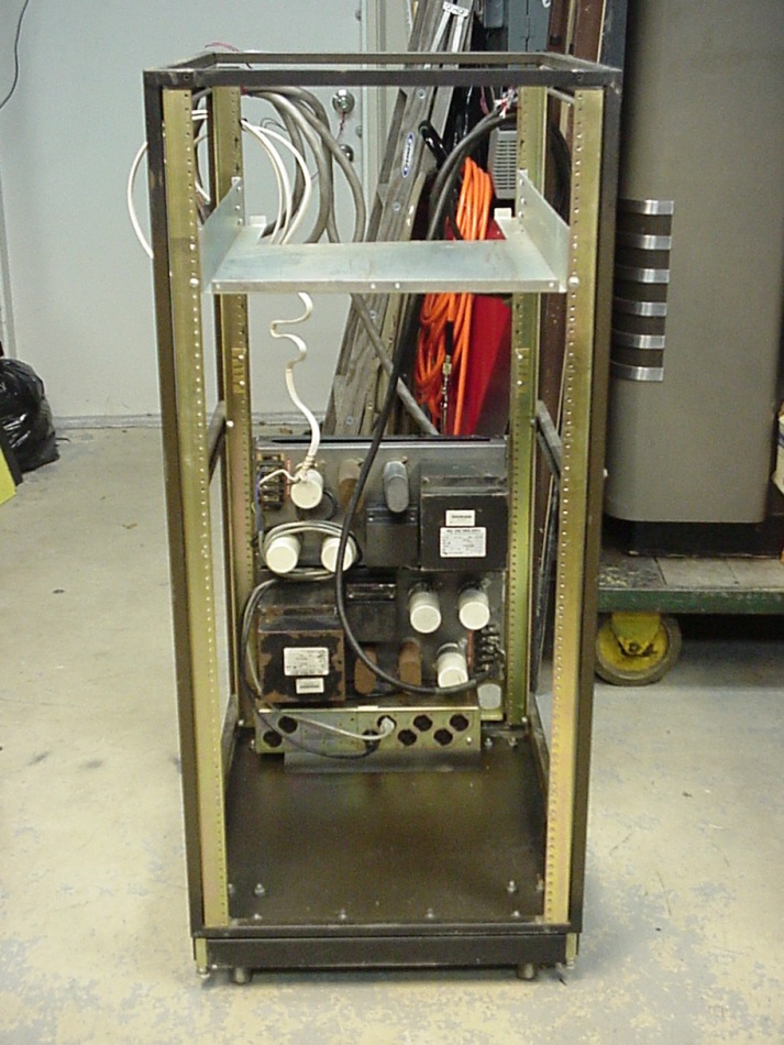
 The lower rear section of the rack was filled with the two Sola 24VDC 25A fixed-voltage power supplies and the AC power distribution panel (bottom unit). They were put in the back to help balance the weight of the units to be put in the front. Since these 60-lb units are both shallow and not "box-shaped", the easiest way to install them was to lay the rack down, and place them on the rails, then install the screws, and set the rack upright. |
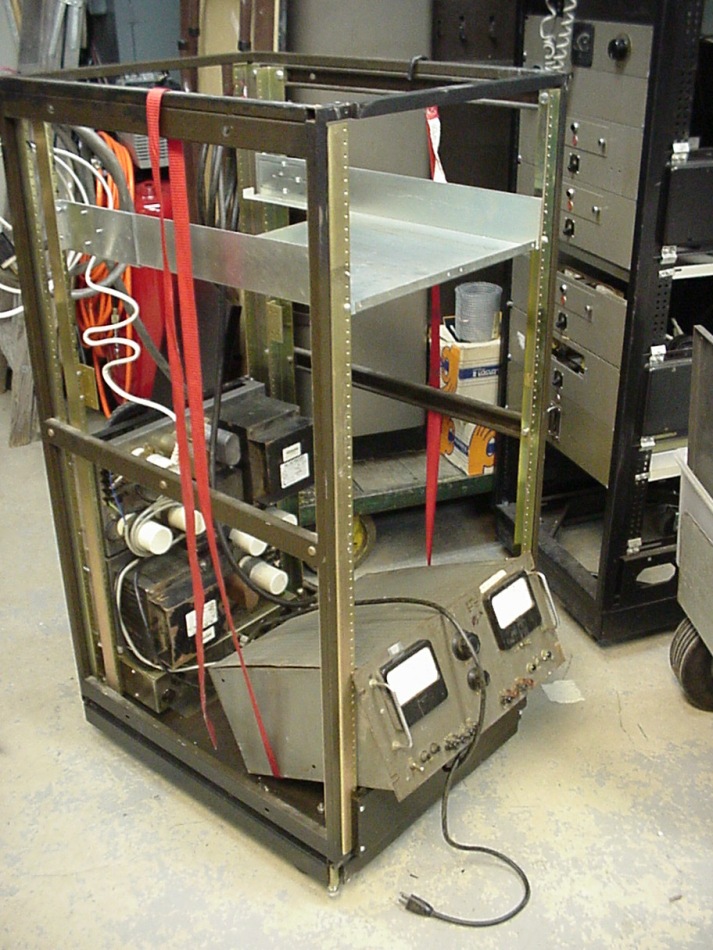 The largest and heaviest power supply, rated 0 to 300VDC at a very solid 0.5A, with a respectable power to weight density of 1:1 (Watt/Lb.), was placed at the bottom. This beauty has seven 5U4 rectifiers and seven 6CD6's for pass tubes. In order to protect its front panel from careless feet, a 5.5" (4U) panel was placed in the lowest position, elevating the supply. The supply was set in place, and a sling made of a cargo strap was passed under it. |
 The sling was pulled to raise the unit to a level position. If the sling does not want to come along, the upward section can be pulled up to help raise the equipment to level. The top screws were started, and the bottom screws then put in and tightened to suck the panel up to the rack. During this process, it was useful to align the holes carefully using a thin screwdriver to adjust the clearance between the bottom of the power supply panel and the blank panel below it. The top screws were then tightened. |
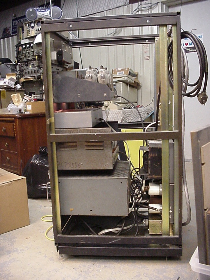 All the supplies were mounted using blank panels between them for convection cooling where necessary. The 24VDC supplies in the back have no control panel utilities, so their outputs will be brought up to the front panel of the rack and terminals will be installed later. Power for the entire rack is controlled by the contactor in the power distribution panel, which was salvaged from a DEC computer rack. The contactor will be wired to the large switch at the top of the rack later. |
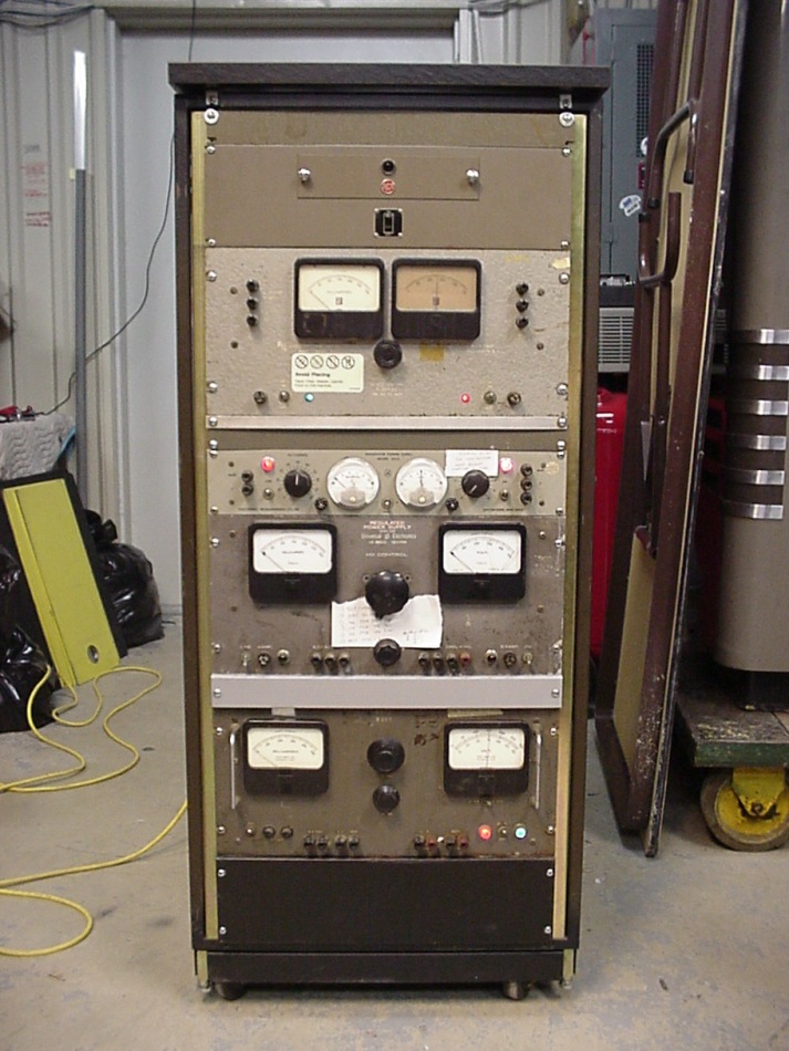 The switch and its panel assembly were salvaged from a 1940's RCA broadcast system (which is a nice touch). This way, all the power can be controlled from the front of the rack. It is always important to have a main power shutoff on medium voltage and high voltage power supply equipment of any kind. The voltages from this system are certainly deadly. The completed rack installation includes a formica top. |
From top to bottom:
The white 'notes' on the second and third power supplies are parts lists.. The 0-100V one was temporarily repaired, but the one below it needs a few more parts before firing it up. Keep in mind most of this equipment is about 40 years old. |
KD5OEI