The 25KV power supply need not be high-current. The power input is 16J/1, so a low current supply can be used to charge the main capacitor. Something simple and inexpensive like a 10KV/20mA neon sign transformer with a voltage doubler, used in conjunction with a variac will do fine and can supply more current than necessary.
The The 1-MEG charging resistor must be of the HV type, since at capacitor charging time, it will have the full 25KV across it. The wattage need not be 25 watts, but beware of too small a thermal mass or it will overheat each time the main capacitor is charged. A string of small resistors can be used as long as their individual voltage ratings are not exceeded.
The 4nF (0.004uF) capacitor (main storage) must be able to withstand 25KV. The 0.005uF/40KV LK400-502ND from Plastic Capacitors could possibly be considered, or as a pair of parallelled 301/1/09000/09T 2000pF/40kV caps from Morgan Electronics.
The peaking capacitor of 500pF/ >25KV might be able to be found as a vacuum cap from an RF chassis like the CFHP-450-55S vacuum RF type from Jennings, or maybe a couple of 301/1/09000/04T 940pF 30KV types put in series for 470pF from Morgan Electronics.
The triggering circuit for the trigatron needs to be worked out after a trigatron is obtained or made. The difficult part as I see it is to fire the trigatron, yet not have the firing circuit either dissipate meaningful energy from, nor be damaged by, the exposure to the 25KV potential in the high-current arc between the main electrodes.
The TEA-CO2 pulsed laser works at atmospheric pressure. Specified Output pulse power on this beauty is about 1 megawatt and average power is about 2 watts at a 1Hz repetition rate.
More can be found out about this laser here, including references to several papers on the subject. Dr. Trtica at the Institute was very kind to advise me on this laser.
The CO2/N2/He gas mixture in the cylinder is CO2/N2/He=1/1/8 (volumetric %). Other mixtures can be used, e.g. CO2/N2/He=1/1/5. The laser does not use a heat exchanger or gas recirculation system, but it could be applied in order to lower gas consumption.
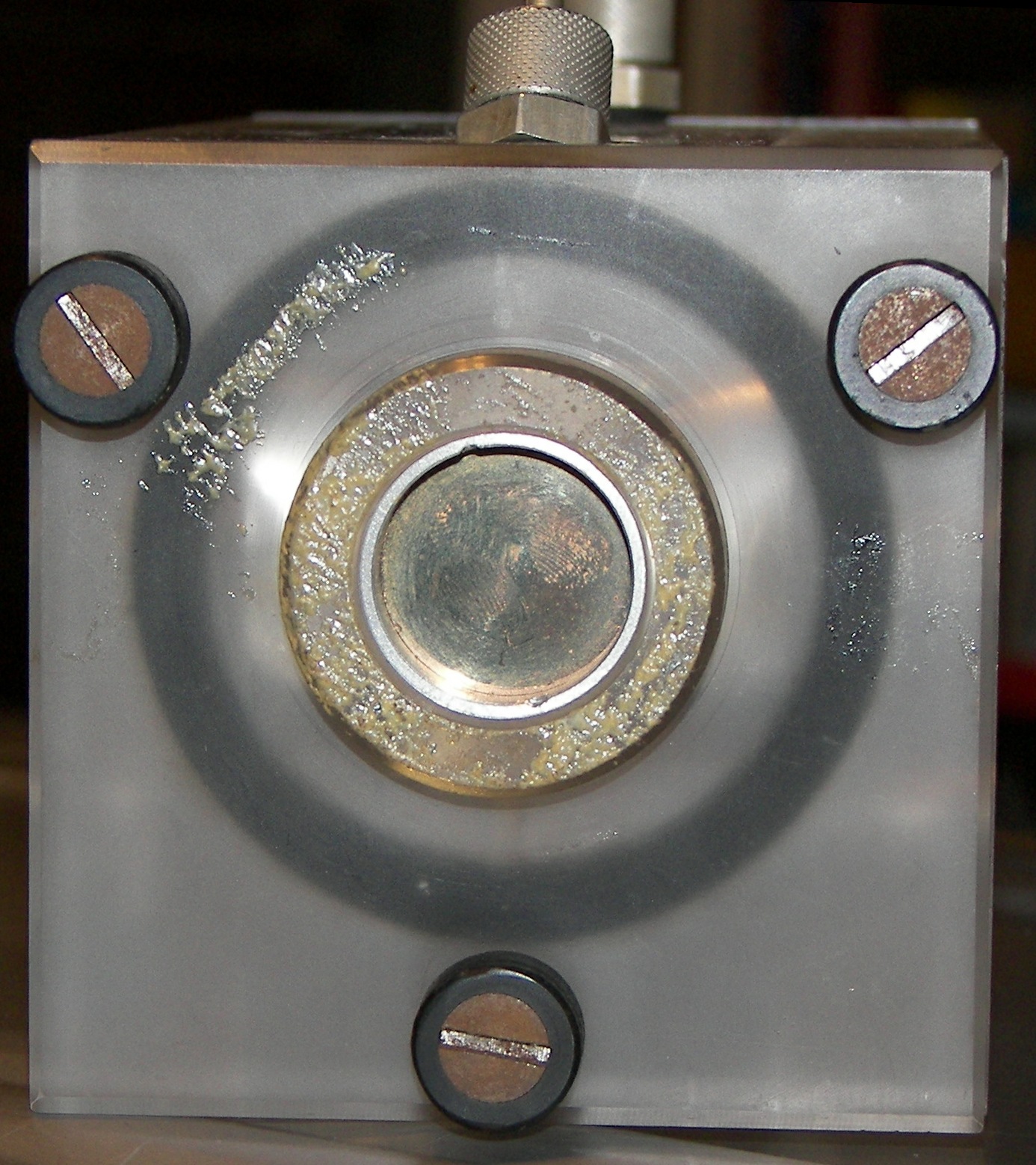
My next step is to find the papers and read them. No doubt they will apply to the priciples of this laser. I did try to clean the output coupler with no real success. The 'dirt' seems to be in or deposited to the outside-world anti-reflection coating. Perhaps it got dirty and no one cleaned it and over the years the dirt just became part of the coating. Maybe the laser was fired with the dirt on the mirror and it got baked on.. I don't know what really happened. If I have to, I can either get the output coupler reworked or I can replace it. Niether will be inexpensive.
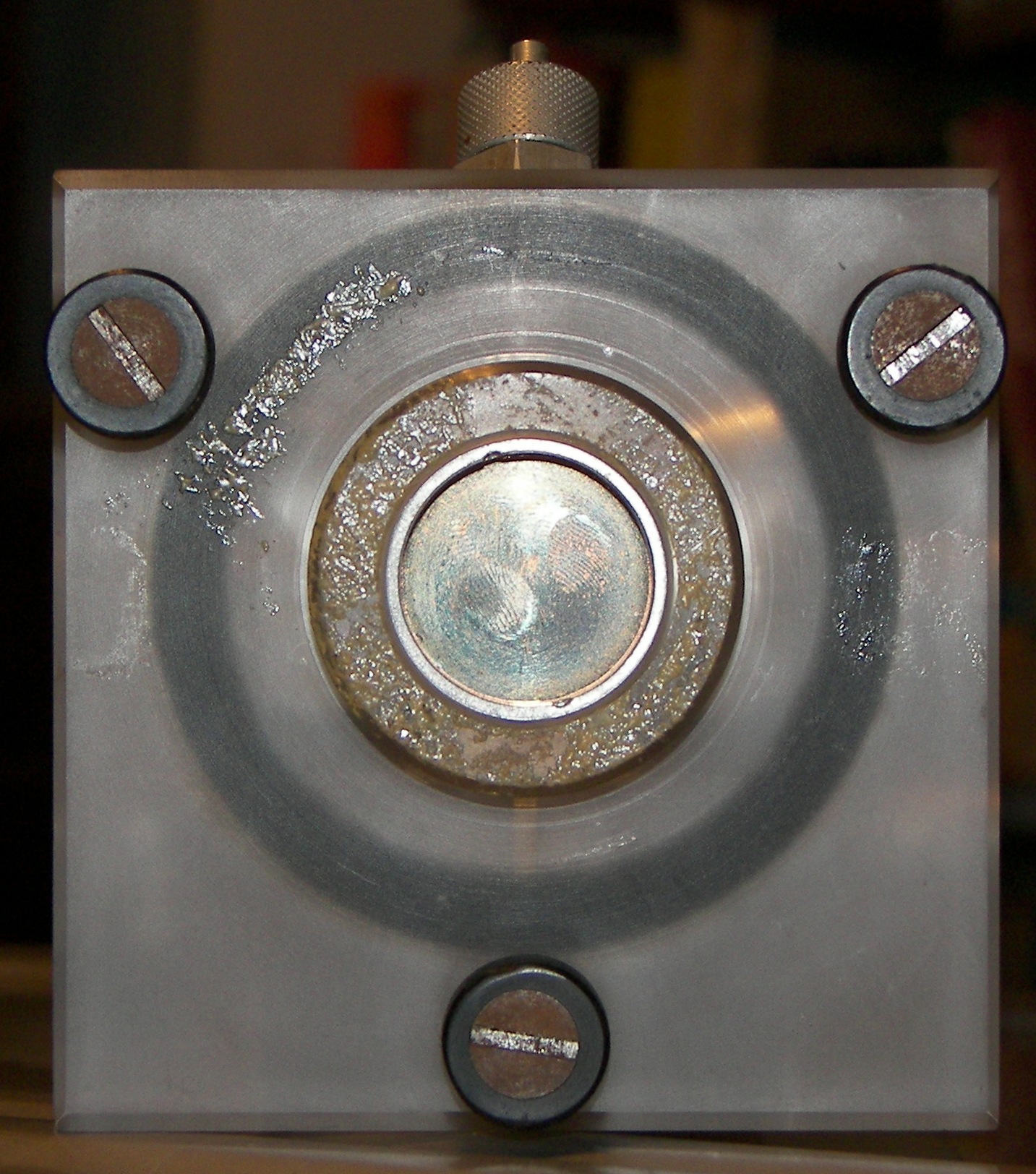
Output coupler. It is dirty, quite a few fingerprints. I did not notice this in the auction, but with such mirrors, the camera angle affects what you can see. I have tried to clean this mirror with several chemicals to no avail. Otherwise, optics and innards seem fine. |
Output coupler. |
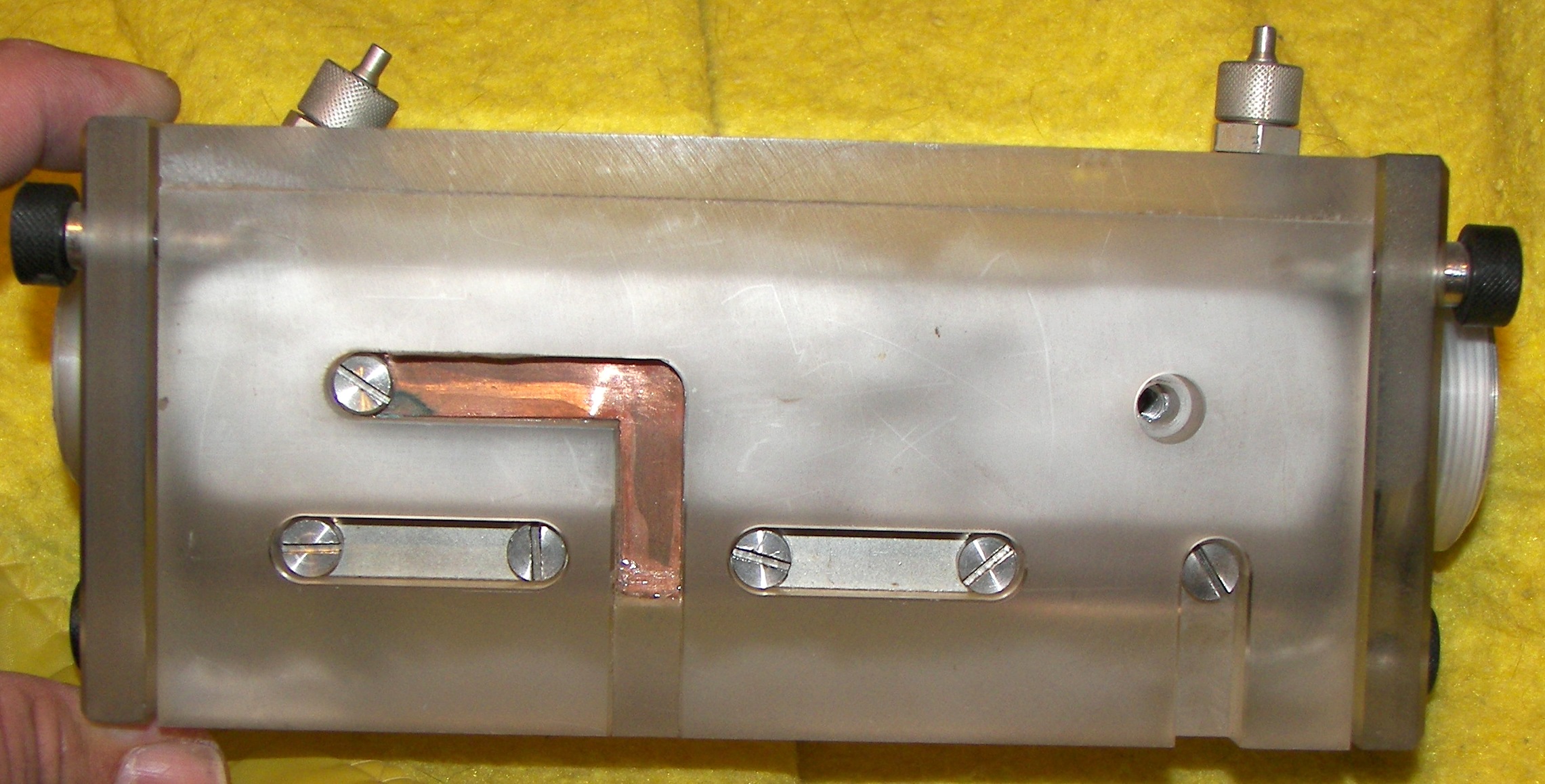
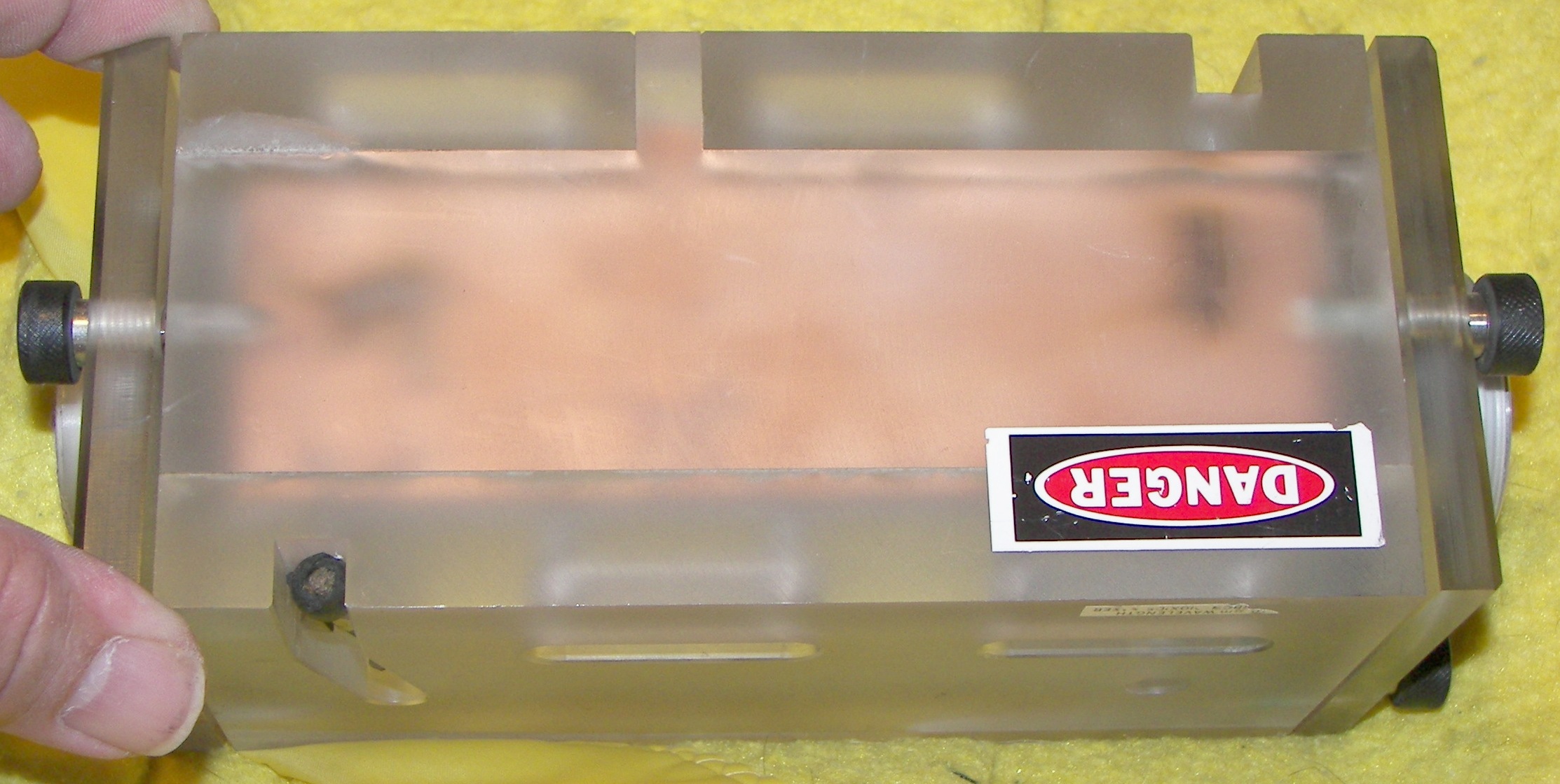
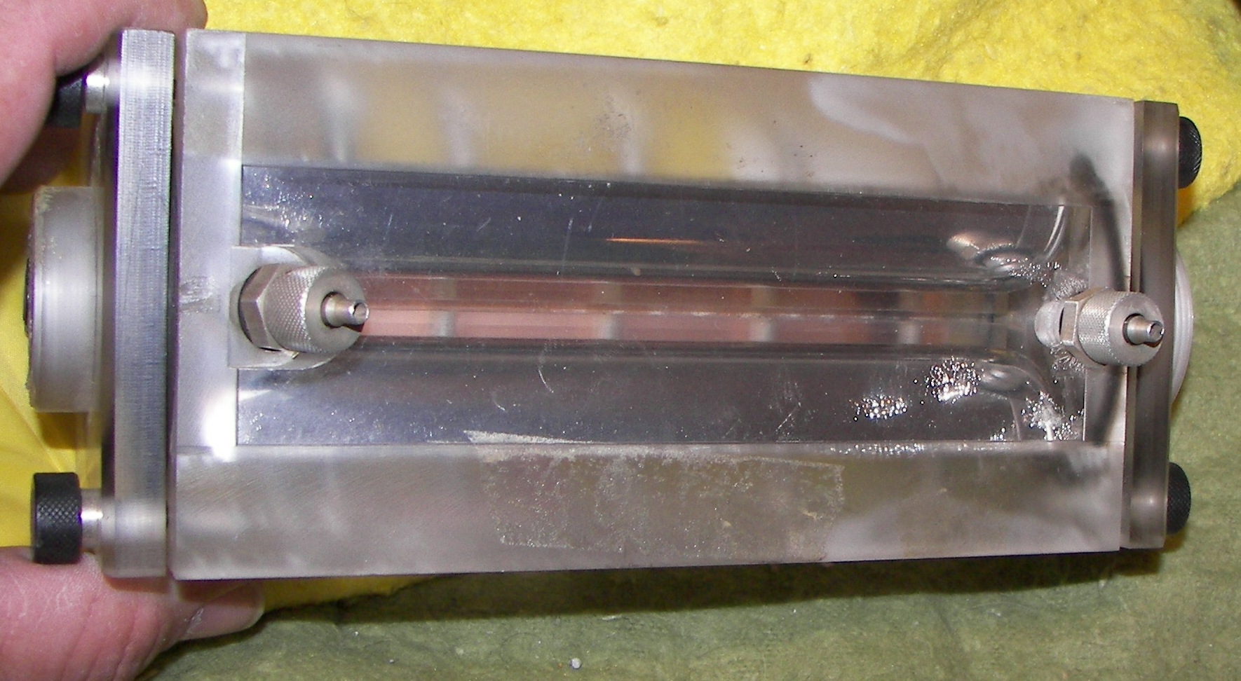
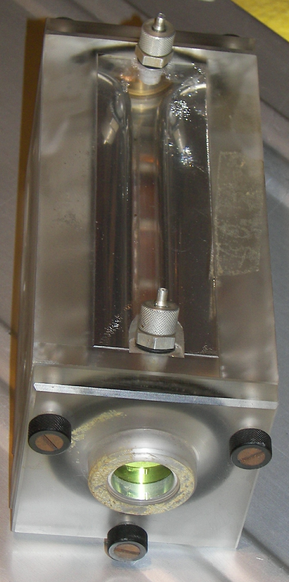
Bottom view. One screw is missing from one the the main electrodes. The other screws are the pre-ionizer section, a series of spark gaps. The copper foil goes to the common section of the built in preionizer capacitor. This is also the ground point of the laser. |
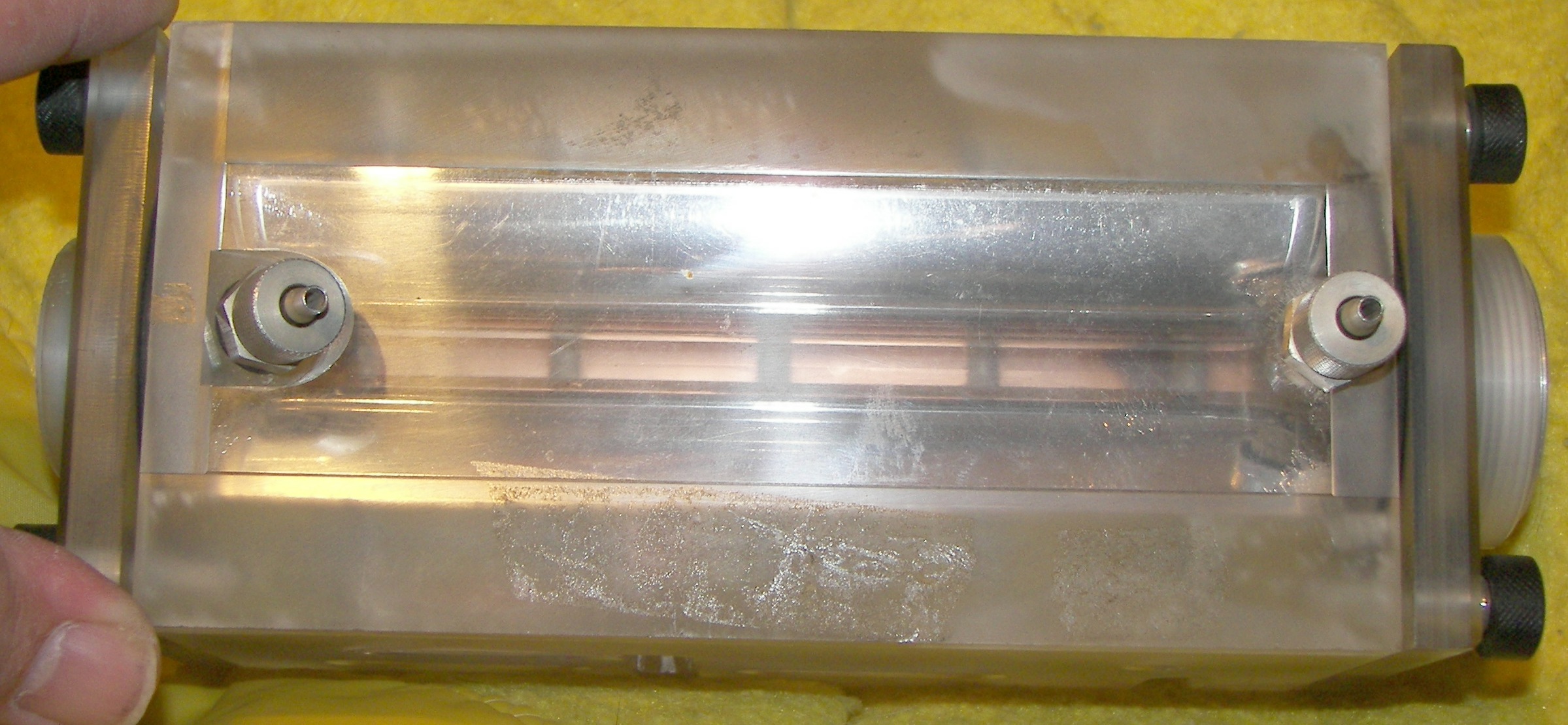
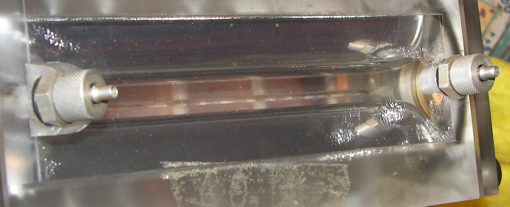
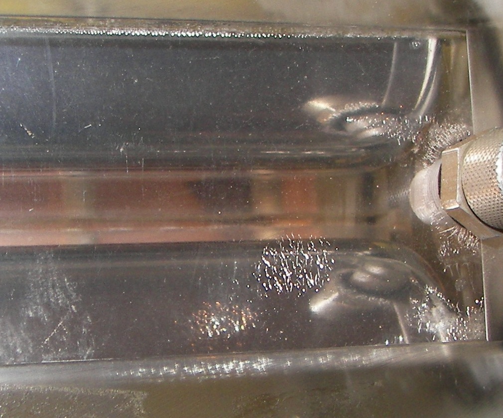
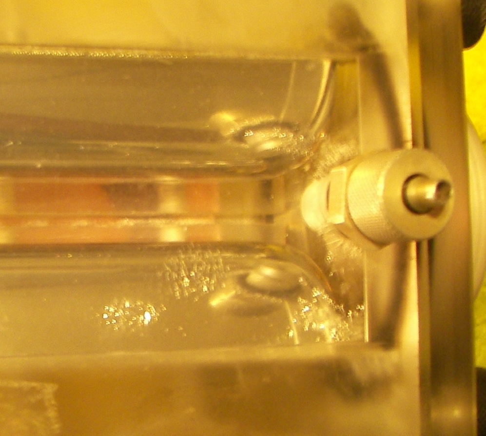
right side. A good view between the electrodes. There is some checking of the plastic but it is on the surface. |

top view. The cut cable is the high voltage pulse input. This should be connected to the main discharge capacitor by very short leads. A value of 4nF is good for starting, and no more than 8nF is to be used. I will be happy with 4nF, since my goal is to have a reliable and long-lasting laser. Why push it? |
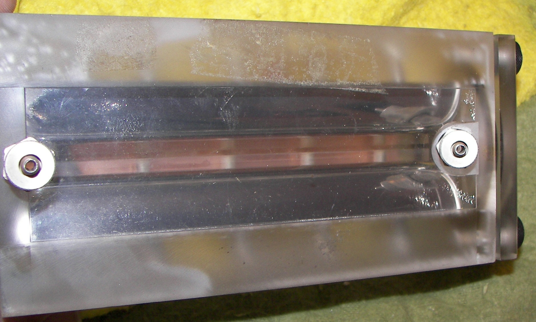
left side. This is the common plate of the preionizer capacitances and is part of the ground. |

the image shows the surface checking of the plastic. It should do no harm. |
the OC looks pretty good in this one. Notice the beautiful profiled and polished electrodes. |
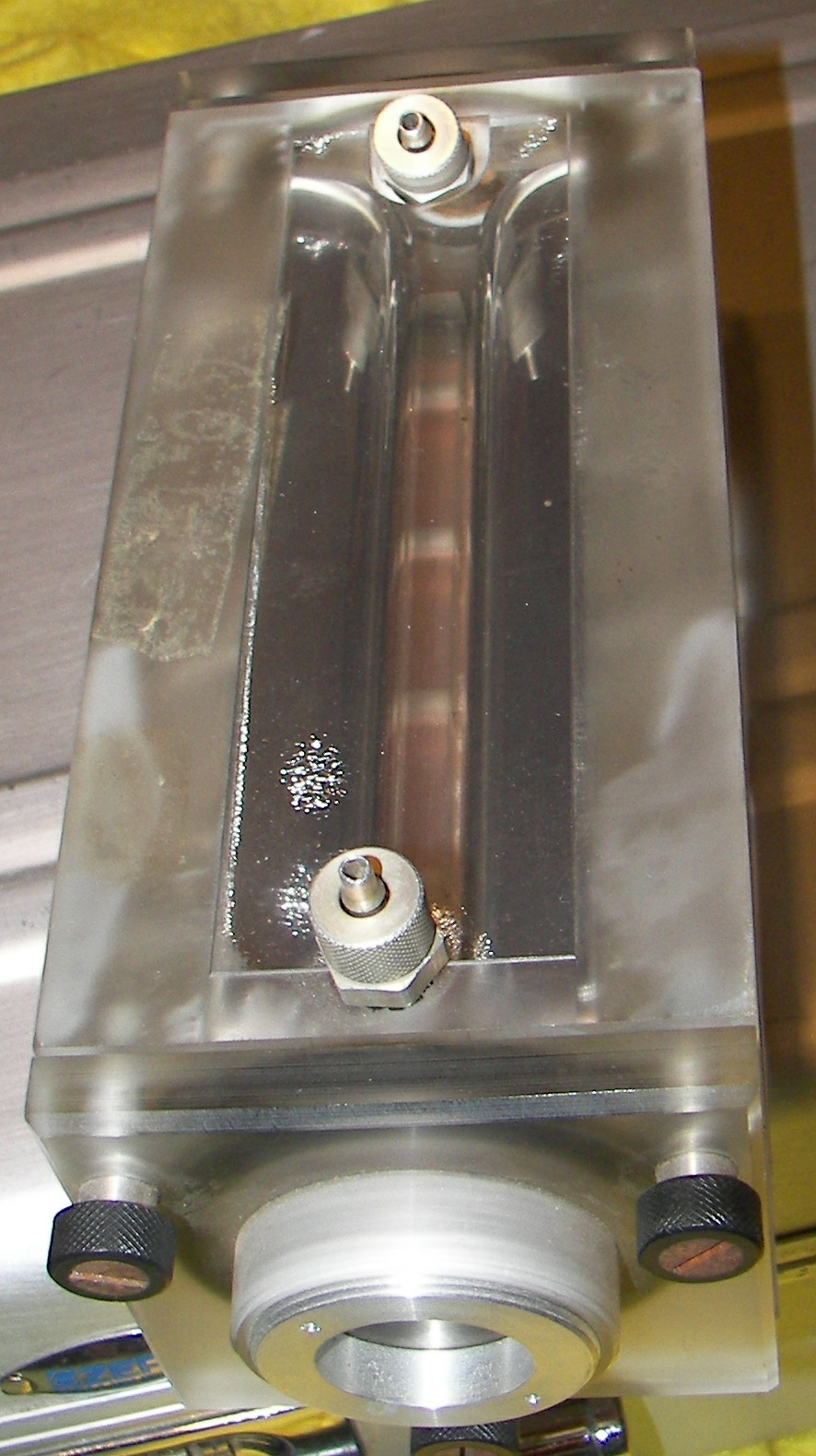
The next few pictures try to show the darkened area on the preionizer section. Whether this is cause for concern or not is unknown. have to test the preionizer. |
|
|
Please notice the milled preionizer gap in the back, which is hiding a series of needles. |
|
|

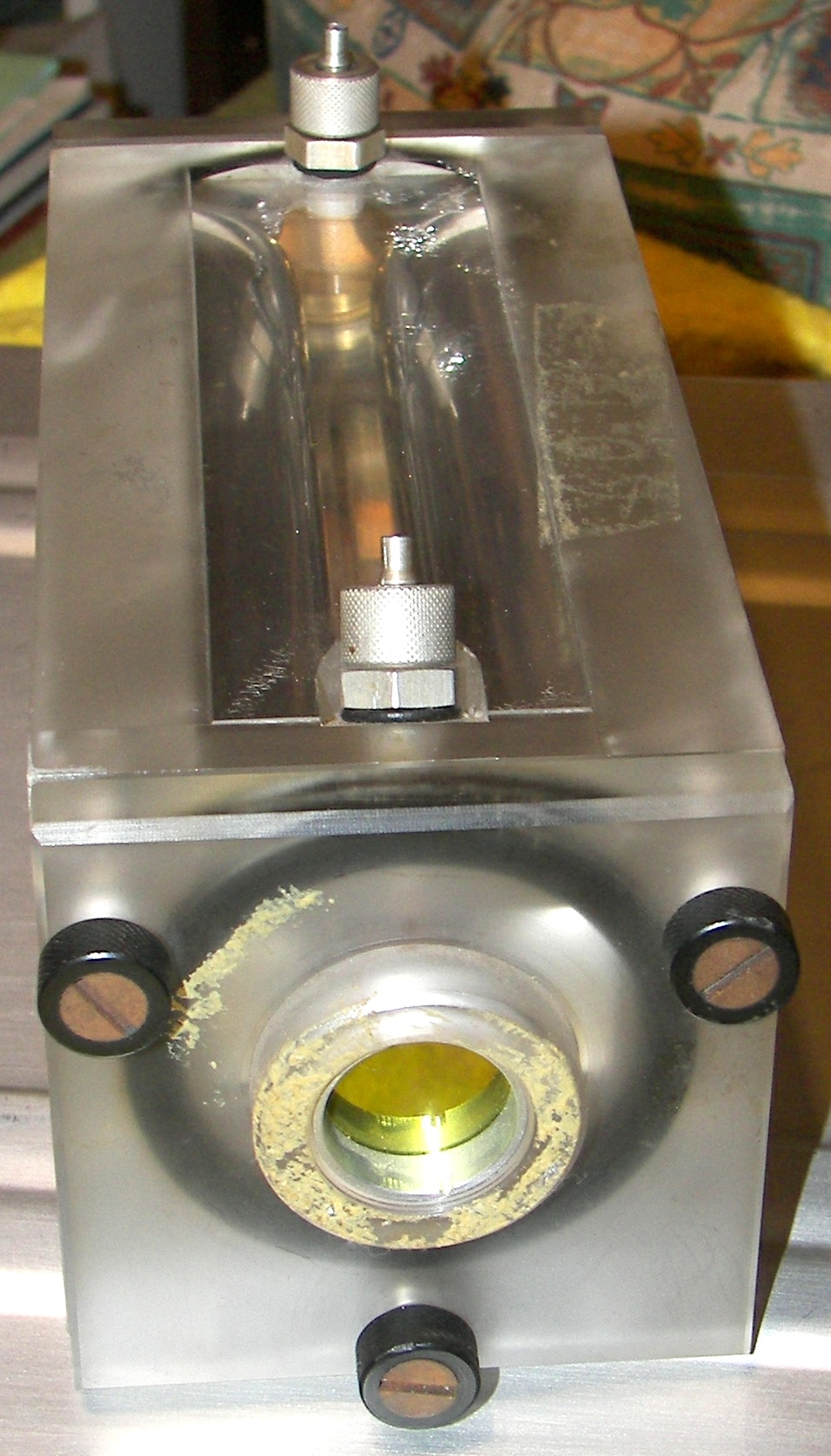
the business end.. The OC is germanium with gold coating inside and AR coating on the outside. |
|
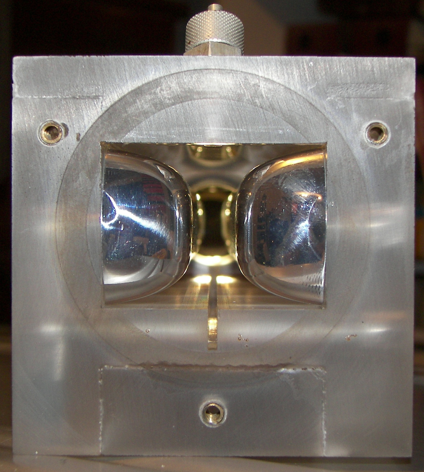
I was able to remove the output coupler block and take this image of the total reflector. It appears to be a gold plated germanium mirror. The slot at the bottom is where the preionizer lives. |

image swiped from the manual: resistor is about 1 megohm, first capacitor is main cap at 4nF, next four caps are built into laser head with preionizer, and final cap near the electrodes is peaking cap of about 500pF. HV is 25KV. |

|