This diode-pumped Nd:YLF LASER produces >1.2 watts CW at 1047nm and can be modulated as well as Q-switched.

The proof is in the pudding. |

A pair of R2-series power supplies (diode pumps). Only one is used at a time, the other is a spare. Note the laser goggles. Only a fool uses invisible laser beams without them. |
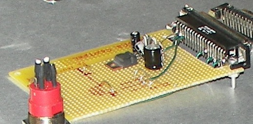
The small home-made board provides on/off, power level, mode, and interlock control for the system and also has several outputs for measuring power, current, and temperature. |

The black box contains the Nd:YLF head and a host of fine optics. The beam exits the silver tube at the top. |

Inside the box |

Md:YLF head with integrated Q-switch |

AO modulator, beamsplitter, power head (left), two mirrors turn the beam back 180 degrees through a spatial filter. |

Next the beam expander to collimate the beam. |

From the expander, to the right and down through a beamsplitter to another power head (left) and further down to be steered into the spot size adjuster. |

The two stepping motors with the black wedges produce a sized beam with a square or rectangular cross section. Square is good when trimming a feature on a semiconductor die, since most features are intentionally rectangular. |

Once the beam is sized, this servo selects the neutral density filter to attenuate the beam so the proper amount of energy is delivered to the work. From here thebeam hits the last mirror and comes up out of enclosure. |

filter selection is confirmed by a unique but simple rotary encoder. |

Back to the laser head, here is the NEOS AO modulator up close. The RF driver for this is shown in another picture. |

The next few images show the equipment that is external to the Nd:YLF laser. These items go between the laser and the work. This is a camera that views the work at an angle. It kooks under the focusing lens, and an illuminator shines light in from the other side. This gives a good view of the work quality. |

Focusing lens and galvos. |

|

|

A photo through the galvo mirros and lens, you can se me waving from the other side. |

The business end of the beast. |

A power measuring head and a IR mirror on an adjustable mount. |

This camera looks down at the work, and sees what the laser sees. |

|

NEOS AO modulator driver and the computer that was part of the laser system. |
Manual for the R2 series laser. |
An XRL semicondutor trimmer was being decommissioned at work and I arranged to remove the laser system. The laser is two-part. The power supply contains the control and metering system, diode pump, and Q-switch driver. The larger assembly contains the Nd:YLF head, AO modulator, two other power measurement heads, a beam expander, a beamwidth control, and an attenuator. Additionally, there is a video camera for observing what the laser sees, and a video camera for watching the work from an angle, and the focusing (work) lens and two galvos for steering the beam through the lens. The beam was originally sent to an X-Y table mounting the observation system and focusing lens and galvos, but the table was not retrieved. A dual-axis interfereometer made by Zygo was used to position the system. It is described elsewhere.