|

|
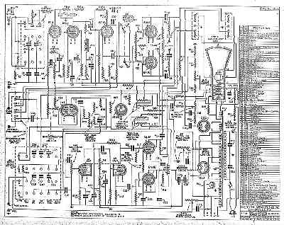
If ever there was a simple to build scope that had a balanced amplifier to give the experimenter some gain, without being too touchy and without needing special parts, the Precision ES0500 or 500A would be a good example.
Yes we are talking about using vacuum tube circuits and many people are not familiar with them. But they offer simplicity at high voltages and are forgiving of mistakes. The tubes in this model are usually easy to find. If you would rather look at a fairly equivalent solid state design, you can see one here.
In case one wants to build something more along the lines of a modulation scope for ham radio, it is simple to just make the power supply and sweep circuit, and leave the vertical deflection out, using an RF coupling method to direct a tiny amount of the transmitter power to deflect the beam. Some modulation scopes don't have a sweep circuit, but instead use the 60Hz AC voltage from the transformer secondary. This is not the best method due to a fixed sweep rate and the non-linearity of the method (a sine wave is not linear), but it is the cheapest.
If you just want to study a high-gain, high-bandwidth tube circuit capable of making >200 volts output, the vertical amp is a good example.
The 5CP1 CRT may or may not be easy to come by. Many others can be substituted with only minor changes in the design to accommodate variations in bias, grid voltages, and the high voltage. Good resources for CRTs are here in these web pages and inside these tube manuals:
inexpensive surplus CRTs
CRT phosphor color chart
Thomas CRT catalog
Sylvania 1943 and 1949 Tube Manuals
Sylvania 1959 Tube Manual *most comprehensive manual
A couple of things to keep in mind when making your own scope are that the rectifiers can be replaced with solid state diodes, and that the filament transformer for the CRT must be able to withstand whatever negative voltage is applied to the cathode. Note in the circuit that the cathode is at a negative voltage of about 1000 to 1500 volts.
This 1951 design has a sweep speed up to 30KHz and the bandwidth is likely no more than 1MHz. The schematic does not provide voltages, so it is mainly a giude to the architecture. The 5CP1 CRT does not require a high Post-Deflection Anode voltage but instead it is using the 300-500V that is used for the deflection amplifier plates. It can handle up to 4000 volts from cathode to PDA, but here it is running about 2000V. Some CRTs do require a higher positive voltage (+1000 to +8000), and this helps with the brightness. The main thing to note when scaling CRT electrode voltages up or down, for a specific CRT, is that the ratio of voltages between the cathode and the last element in the electron gun (in this case the last element is pin 9, conected internally to the the second anode and G2) should be observed. The PDA voltage should be above this value by at least the most positive level attainable by any deflection plate, and that is what they have done in this design, rather than adding a separate positive HV supply of 1500-2000 volts.

|

|