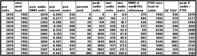
Table 1
The values for figure 1 were computed from entries in table 1. This document will not go into the math behind this, but the numbers add up. If you think you see a mistake, please notify the administrator at the contact on the main page of this site.
The relationships between the various signals in the RF PA power supply circuit, including the modulation signal, as used with a perfect power supply are shown in figure 1. In order to show the linear relationships, the magnitudes of some of the signals were multiplied by decades as shown in the figure.
The RMS audio voltage and the PSU (power supply unit) DC + RMS audio voltage, and PSU current (mAx10) lines are parallel.
The Peak audio voltage and the PSU DC + Peak audio voltage lines are parallel.
The RMS audio wattage, RMS RF wattage, and PEP RF wattage do not increase linearly with the modulating voltage. This is due to the factor of the current components of these wattages, which is multiplied with the voltages. Modulating power is related to the square of the modulation percentage (after Terman).
The PSU wattage variation with modulation is linear because the current from the power supply increases with modulation, but the voltage does not.
The nonlinearity in the "virtual" load resistance seen by the power supply is due to the nonlinear (with respect to modulation precentage) change in the current drawn from the power supply. As the modulation increases and the plate input to the RF PA increases by virtue of the modulating voltage, more average current flows through the RF PA. As far as the power supply is concerned, this is reflected as a decrease in load resistance at its output terminals. In a perfect Class C PA, Eb/Ib, which is the DC load presented to the series connection of the power supply and the AC signal from the modulator, is constant over the modulation cycle. In practice this is not perfect but it is kept as close as possible (overall feedback around the system is used in some professional equipment to prevent additional distortion due to these artifacts).
These factors illustrate the importance of having good regulation in the power supply. In any simple power supply, as the load increases, the output voltage drops. This document purposely shows a well-designed, very basic, medium size 'heavy metal' power supply in order to avoid confusion due to issues of complex or inefficient architectures such as voltage doublers and series-resonant filtering designs (which are beyond the scope of this document).
Two power supply topologies are shown below in figures 2 and 3. Both use a 5000 volt center-tapped transformer with a source impedance of 163 ohms for each half of the secondary winding and a pair of heavy-duty mercury-vapor rectifiers for low forward voltage drop. The only difference between them is that one uses an LC filter and one uses a CLC (pi) filter. The load resistances shown are immaterial. A wide variety of load resistances were used in order to provide the results. The power supplies were simulated with PSUD II from Duncan Munroe.filter.
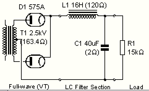
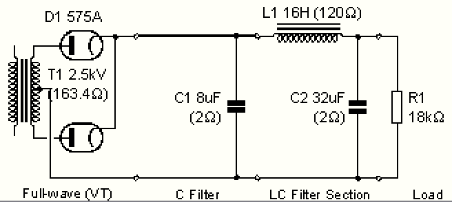
Figure 3 CLC (pi or capacitor input filter)
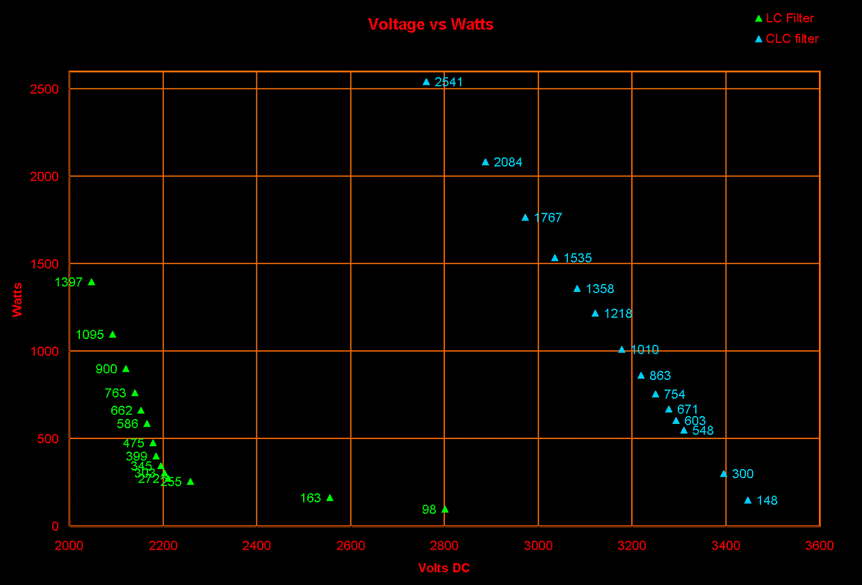
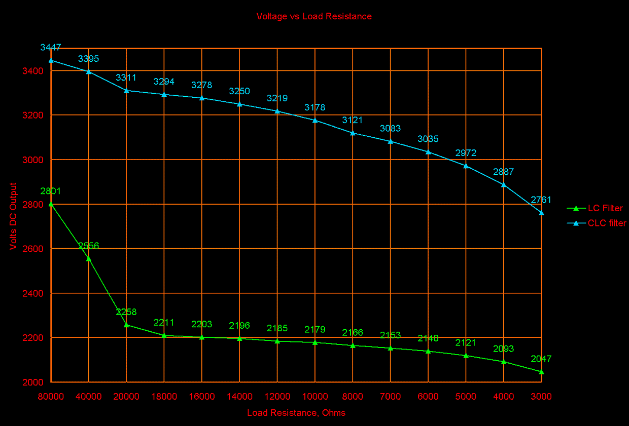

In order to find the real difference between the regulation characteristics of the LC and CLC filters, the AC input to the power supply with the CLC filter was reduced until its output voltage with the 8K ohm load matched the same voltage of the LC power supply with the same 8K load. Then the load resistance was stepped down through the test points to reveal the differences in regulation. A load resistance range of 8000 to 3000 ohms was selected because this area represents the conditions present in the power supply during various modulation conditions for an RF PA stage operating at a typical voltage of about 2000 volts and supplying about 1500W PEP into a load.
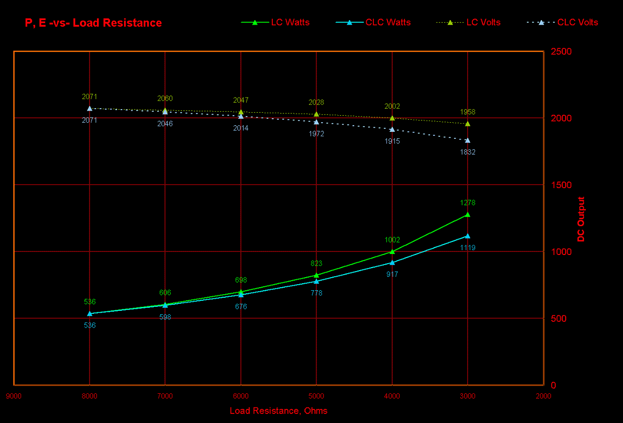
For the purpose of this document, the regulation in percent is calculated by dividing the full-load voltage by the minimum-load voltage, and subtracting the result from 1. [ 1-(Efull_load/Eminimum_load)=%reg ]. The figures below correspond to the modulation conditions (load currents up to 440mA and minimum apparent load resistance of 4700 ohms under 100% modulation) shown in Figure 1.
The voltage delta for the LC power supply output voltage over this range is 53V and the regulation figure is 2.57%
The voltage delta for the CLC power supply output voltage over this range is 122V and the regulation figure is 5.88%
These figures are not exact because the data in figure 1 assumes a prefect power supply, that is, one in which the output voltage does not change with fluctuations in load current. Nonetheless, they are useful when applied to both real-world power supply configuration in order to show the differences between the two.
As previously stated, negative feedback can be applied from the RF output of the RF PA to the modulator input in order to reduce the distortions caused by poor regulation in the PA power supply. Although this is a good solution, every effort within reason should be made to improve the regulation of the power supply design because the better the regulation of the power supply, the less feedback will be needed.
In the example of the power supply with the CLC filter under the conditions in figure 6, when the modulator causes a large current drain on the power supply, the output falls by 122 volts. Instead of the modulator's 2071 peak volts adding to the power suplly's 2071 volts, there is only 1949 volts DC, making the peak modulated voltage for the PA 4020V instead of 4142V and the modulating wave is no longer sinusoidal because the positive peaks flatten slightly. This is not due to modulator inadequacies, but to poor power supply regulation. In the negative direction, the power supply voltage is also less than the modulating voltage (it cannot recover to the minimum-load voltage state between audio half-cycles) and negative overmodulation occurs. The transformer-coupled, choke-decoupled modulation system will approximately balance the difference between positive and negative half-cycles, so that the positive peak is 61V too low, and the negative peak goes to -61V. This can be limited by use of the usual diode, but doing so presents a nonlinear load to the modulator during those times.
One solution is to lower the modulation level so that the PEP input to the RF stage is less than 4 times the carrier input level. 100% modulation can still be obtained, but the modulation, percent-to-percent, will not be linear and the carrier level will decrease under modulation.
Final Comments:
The author acknowledges that the 5.88% regulation figure cited above is fairly good in general and admits to 'splitting hairs', but points out that many HV power supplies, especially those which serve both a modulator and a PA stage, have much poorer regulation. Power supplies with poor regulation, and the noise they contribute to the signal, are the target of this article. One example is the typical voltage doubler power supply which provides 2400V at carrier level, but drops to 2000V at 100% modulation (17% regulation). It is often worse in smaller non-commercal equipment. The B+, supplying both a class-B modulator and the PA, can go from 900V to 710V (22% regulation) each time the operator speaks into the microphone. Ideally, the modulator and PA should have independent power supplies. A very large factor in the regulation performance of a power supply is the impedance of the power transformer. The example power supply has only 163 ohms impedance on the secondary winding. This low value is because the transformer on hand in the examples is rated for about 1 amp CCS on the HV side -it's an old 'pole pig' core. Many transformers used in "1500W PEP" equipment have larger impedances. Another cause of poor regulation is the DC resistance of the choke. The example has 120 ohms DC resistance and a few volts can be lost here. In power supplies, "bigger is better", as it usually translates into lower impedances and lower DC resistances. The spreadsheet used to get the charts and help with the calculations is available as a zipfile. No support of any kind or further explanation of its contents is offered, so consider it a scratchpad or a help for understanding.