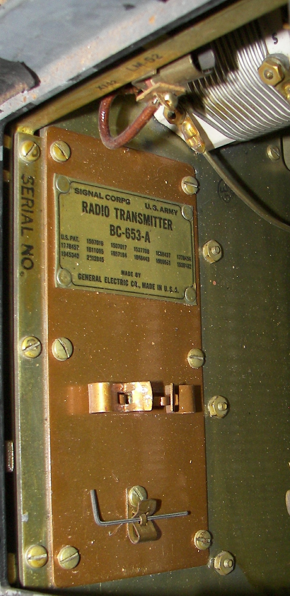
BC-653-A Transmitter
another recycle for good: "rescue, rebuild, re-purpose!"
Home
(scroll vvv down vvv for images)
Description:
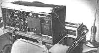
BC-653-A is the transmitter part of Radio Set SCR-506. The accompanying receiver is the BC-652 or BC-652-A. The set was made in 1941.
Applications:
The set could be installed in tanks, trucks, jeeps, or any other kind of ground vehicle. Modes are AM and CW. AM is accomplished by a well designed screen-modulator. The transmitter has 5 channels. 4 are preset and one is set by a VFO. The operator can selct any of these five channels with a single switch. The BC-653's dimensions are 25.5" long x 12.5" tall x 14" deep and it weighs about 100 LBs.
Frequency Range:
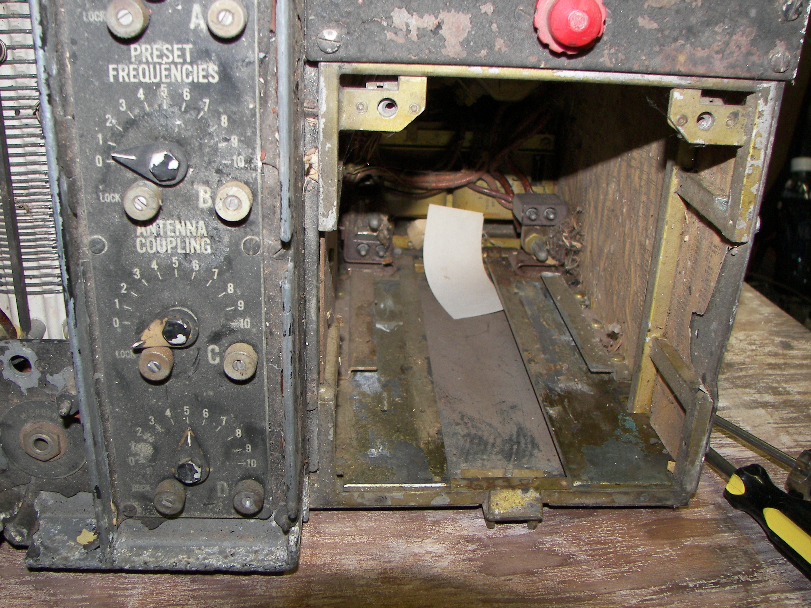
2.0 to 4.5Mc (126 channel assignments spaced 20KHz apart) in four preset channels A,B,C,and D, plus one VFO selection covering the same range in two bands 2-3MHz and 3-4.5MHz. Although channel assignments are intended, each channel unit has infinite granularity and can be tuned to any frequency in the range. The accuracy is as good as the operator's ability to precisely turn dials.
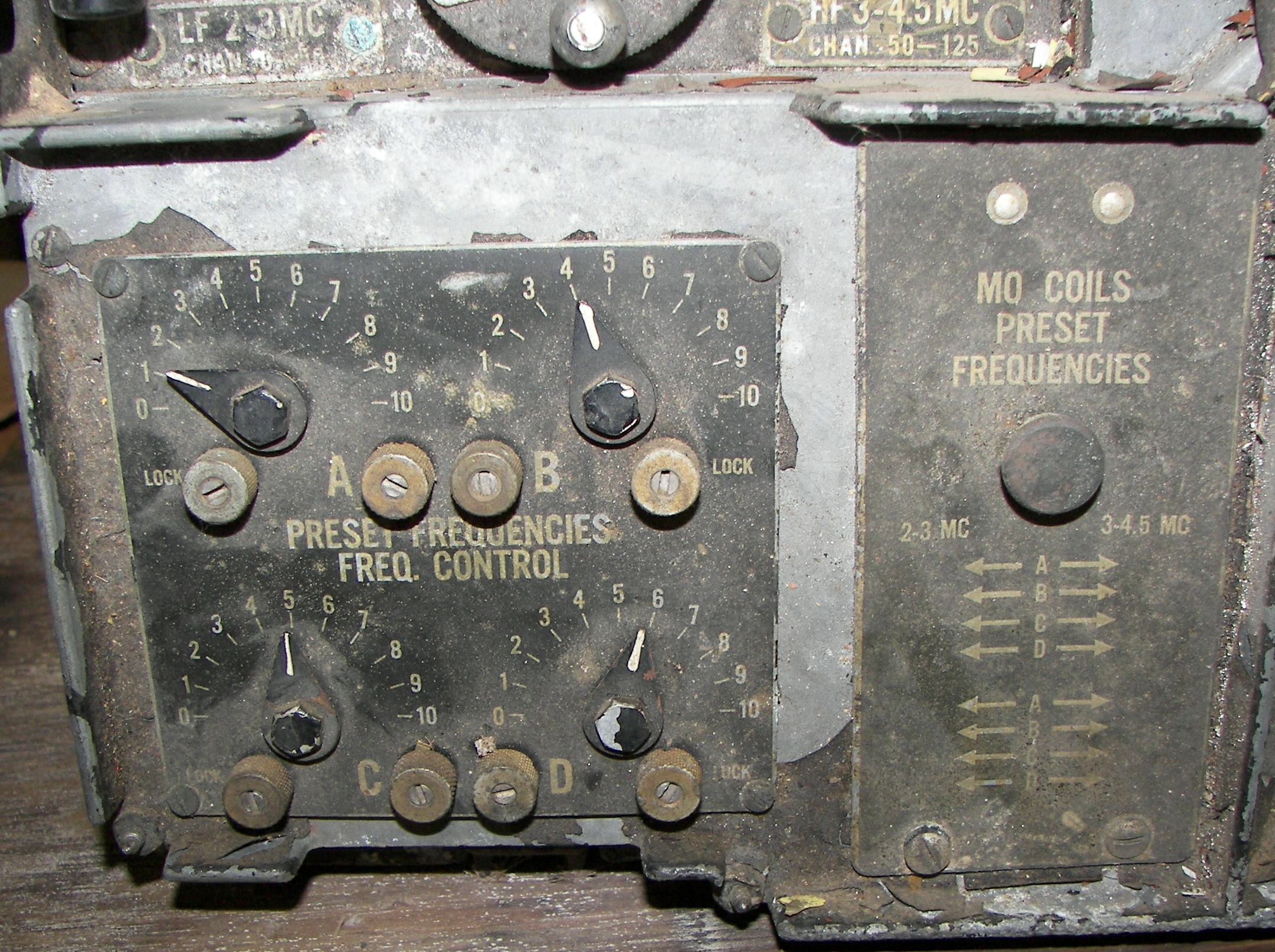
Tuning:
The four preset channels are tuned in the VFO by LC circuits using jumpers to select the coil for the band and variable capacitors to select the frequency within the band. The capacitor position is locked by a screw once the frequency has been tuned. The VFO operates in either of two bands selected by the LF and HF positions of the channels switch.
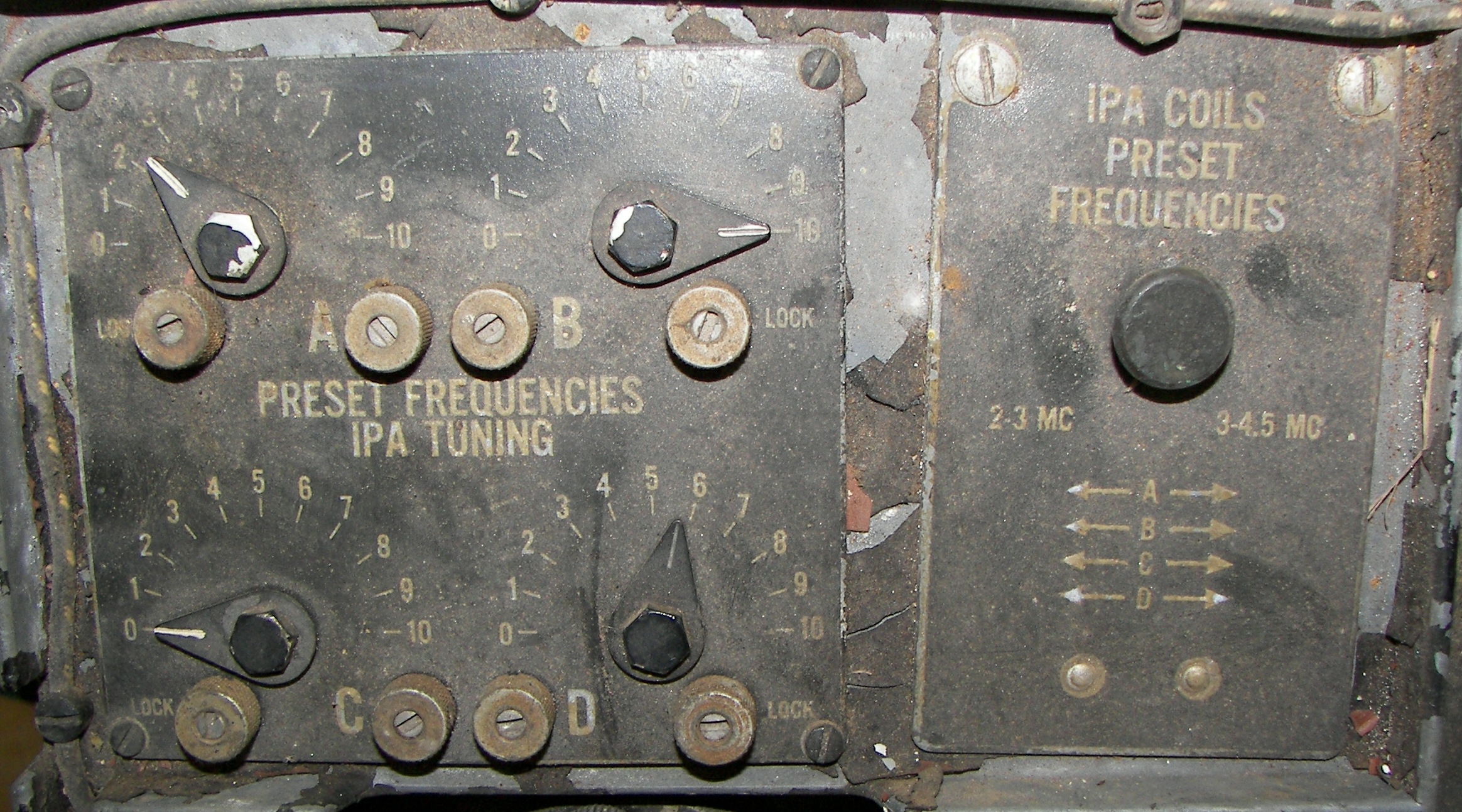
The same arrangement is used for the IPA plate tuning.
The PA tuning employs one variable capacitor for the VFO position and one variable capacitor each of the channel positions. The matching network is a C-L arrangement like a pi-network but with no loading capacitor required. The L section is composed of a quite large inductor L143 with multiple taps, each sliding on its own bus bar. At the top end, 4.5MHz, L143 is out of the circuit. Another coil, L145, provides the L component at this extreme. The antenna is a fixed whip.
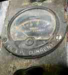
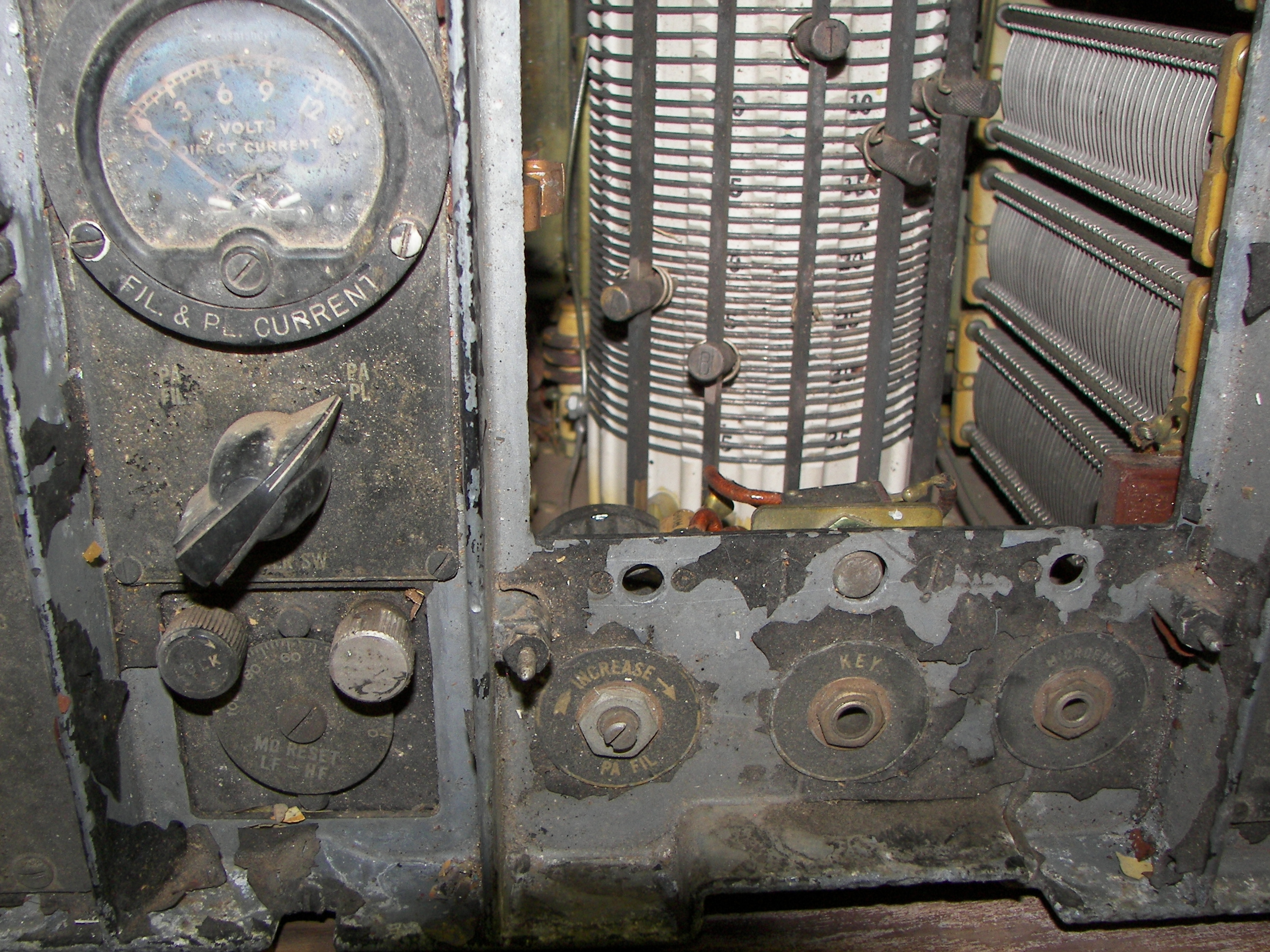
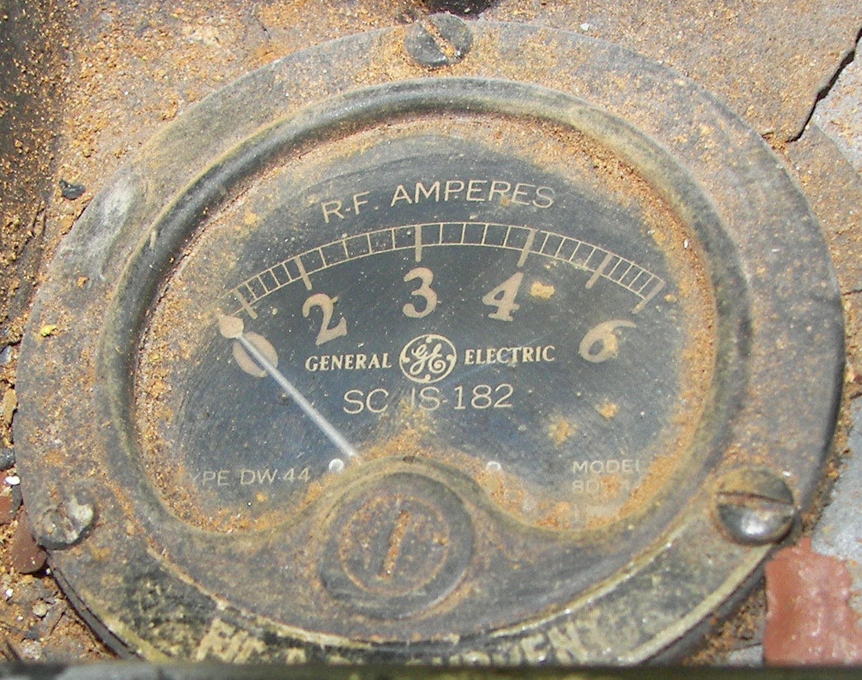
Tuning of the PA is monitored by M140, a 6A RF ammeter, which is in series between the cold end of the PA tuning capacitors and ground.
T/R switching:
K161 is a shaft-based multicontact relay and controls all T/R functions including antenna switching for the receiver.
K160 controls the dynamotor power input and is energized by K161.
12/24V selection:
S164 is set to provide correct relay and heater/filament voltages for the set.
Heater/Filament power:
The two 1613 (6F6) tubes are wired in parallel and this combination is in series with the 807. The string uses 12V.
The two 814 PA tubes require 10VDC. R168 and R169 are ganged together and adjust the filament voltage for the tubes. The circuits are placed in series for 24V operation.
Modulation:
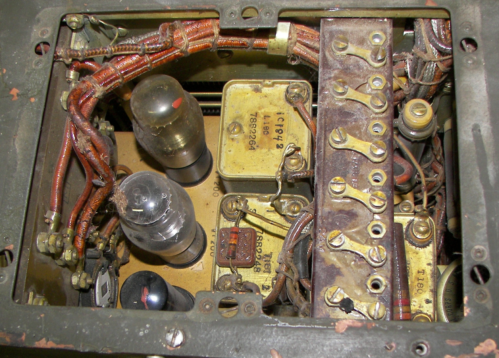
A carbon microphone is used. Its power comes from the 10VDC developed across the filament of V140. Any unanted noise is filtered out of this by L180 and C182. R190 sets the modulation level. The voltage developed across R190 drived T181, the audio input transformer. The secondary ov T181 drives the control grid of V180, the modulator. T180, the modulation transformer, has three windings. One (term 1-2) is the plate winding for V180, one (5-6) is an audio output to the mount and th an aux. receiver, and the remaining one (3-4), paralleled by a 7500 Ohm resistor R189, is in series between the PA control grids and their power supply. The modulator is powered by approximately 360VDC.
Mode Selection:
S160 selects the mode. OFF, TUNE, CW 1/4 POWER, CW FULL POWER, VOICE.
PA Mode Voltages:
In TUNE, a negative voltage is provided to the PA screen grids. In CW 1/4 POWER, R143, a 56K resistor, is placed in series with the 350V supply to the screen grids. in CW mode, the screens are connected to 350V. In VOICE, about 200V is applied to the screens.
Bias:
Negative voltages are supplied by resistors R160, R176, and rheostat R177 which are in series with the dynamotor negative end and GND. R177 is bias adjustment for the protection of the IPA and the MO. PA bias is greater and is fixed.
Power Input:
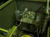
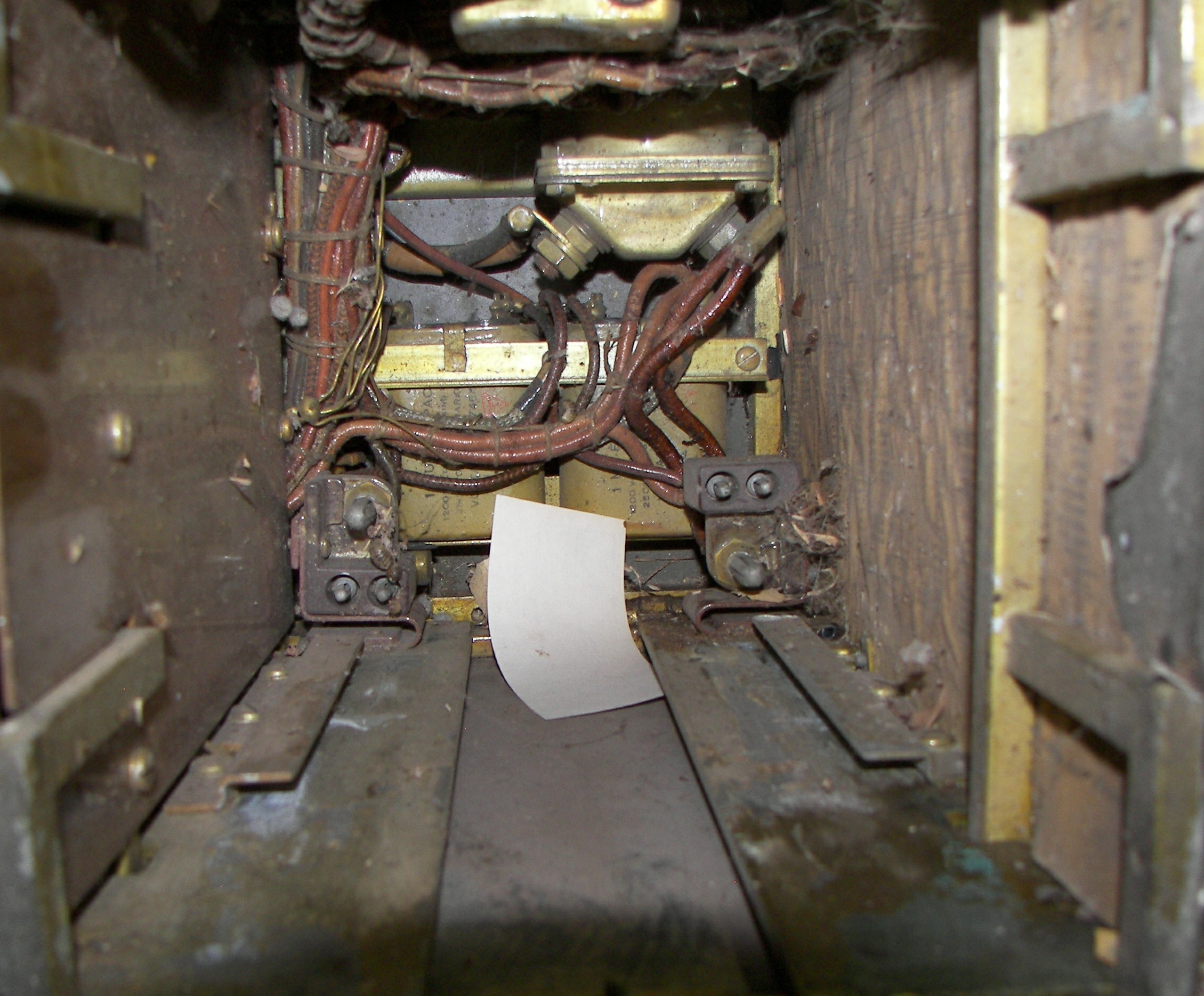
The set is powered by an dynamotor DM-42 (12V) or DM-43 (24V) dynamotor which fit into the open bay on the lower right. The dnamotor supplies 460 VDC @ 260 ma and 925 VDC @ 220 ma. For modern "wall-plug" use, the set requires 12/24, 500 and 1000VDC. The manual is TM 11-630.
Power Output:
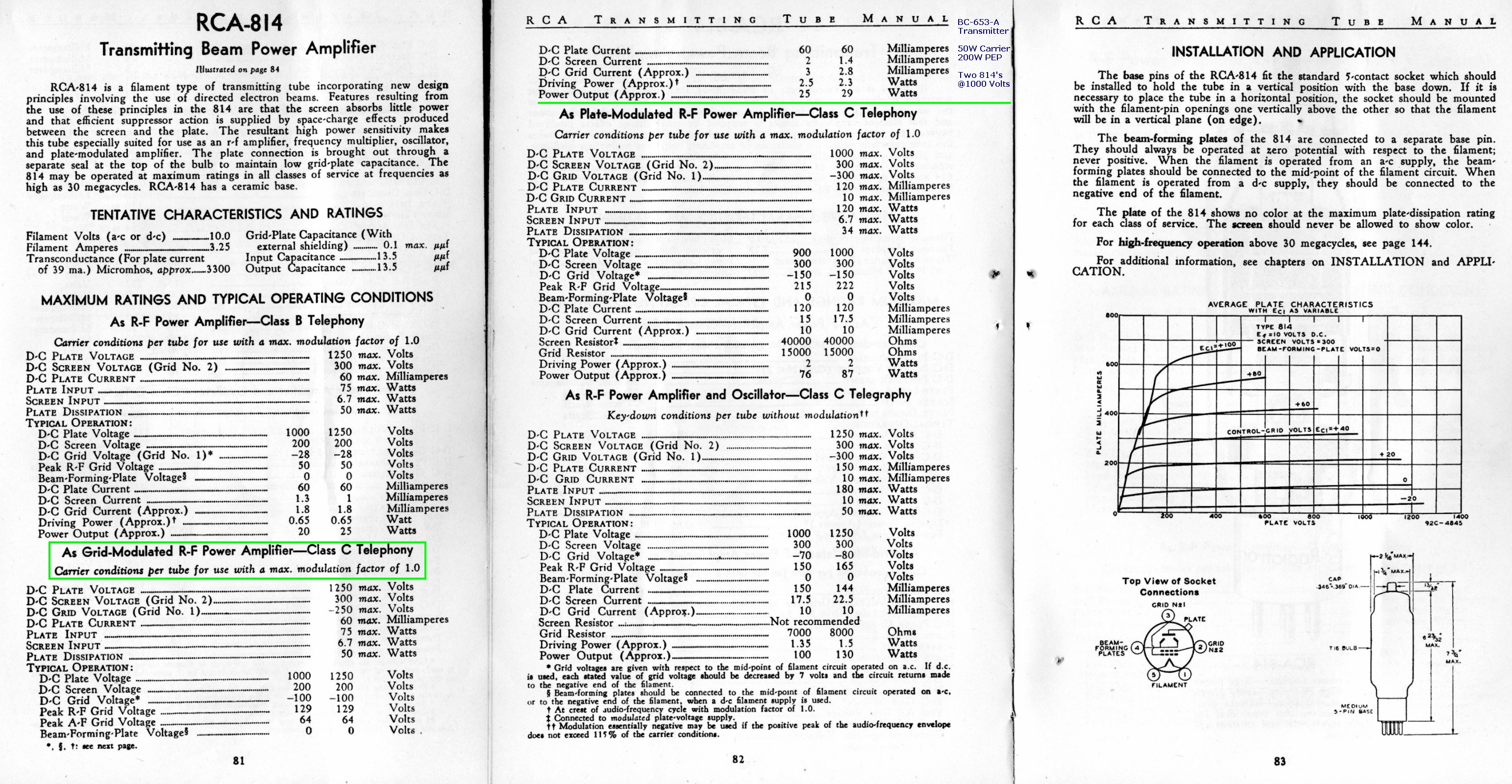
The manual states 25W AM (carrier, 100W PEP) and 50W CW. These are conservative ratings for the powerr amplifier tubes, since the RCA tube manual gives a figure of 50W carrier (200W PEP) for the pair of 814's in grid modulated service at a plate voltage of 1000V.
Tubes:
2 x 814 (VT-154) RF power amplifier
1 x 807 (VT-100) RF IPA (driver)
2 x 1613 (VT-175) MO/VFO and modulator
2 x OC3 (VT-200) voltage regulators
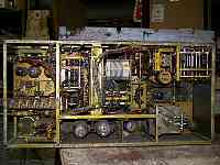
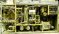
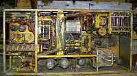
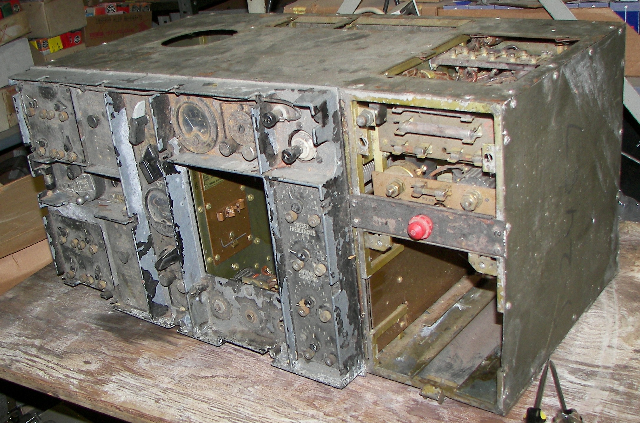
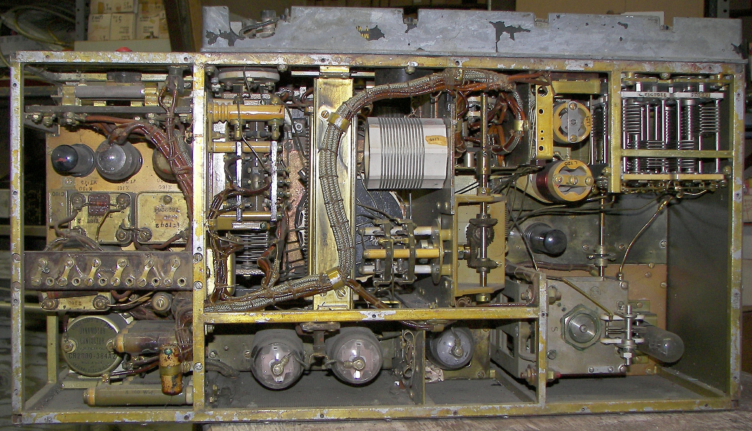
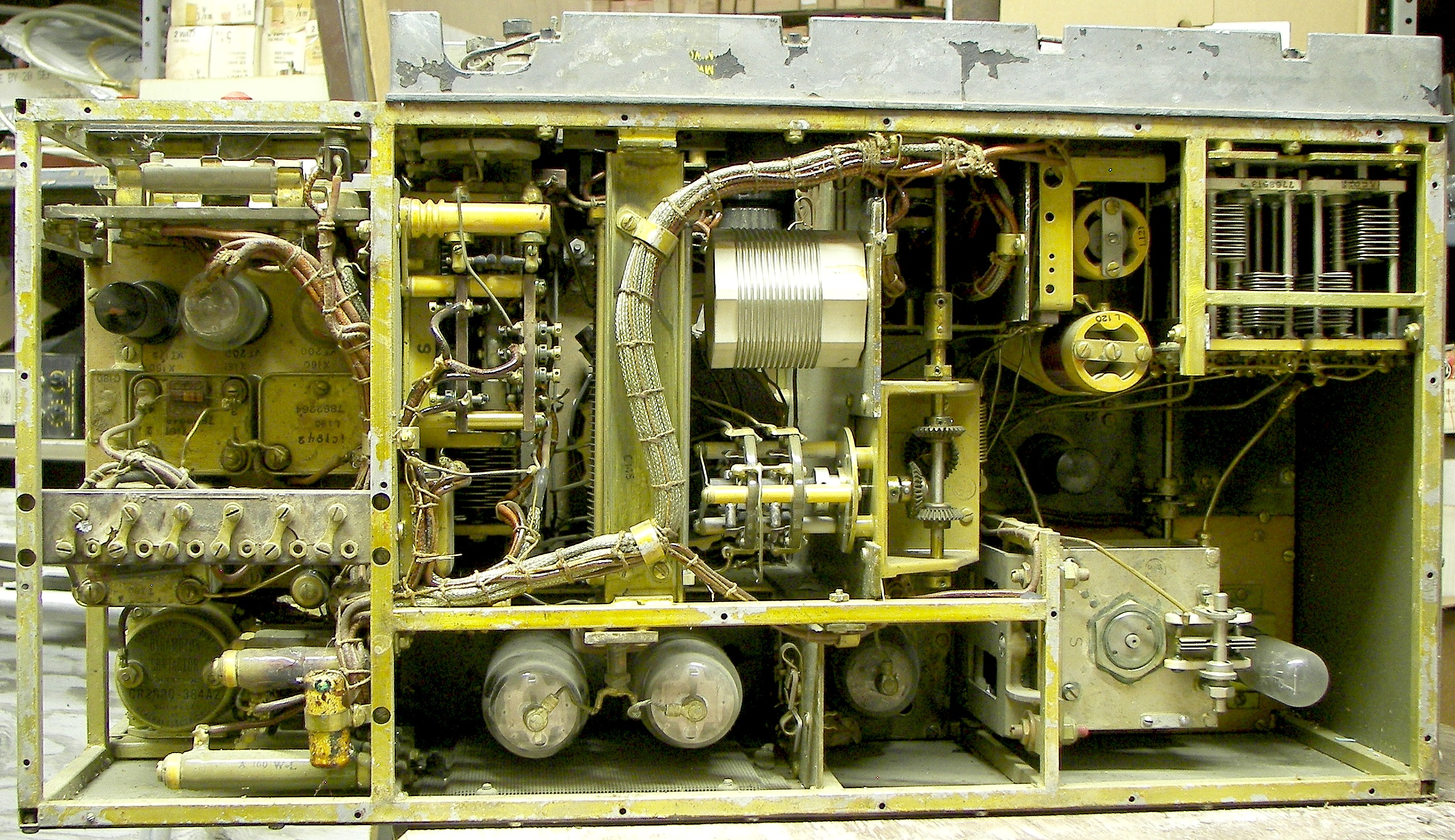
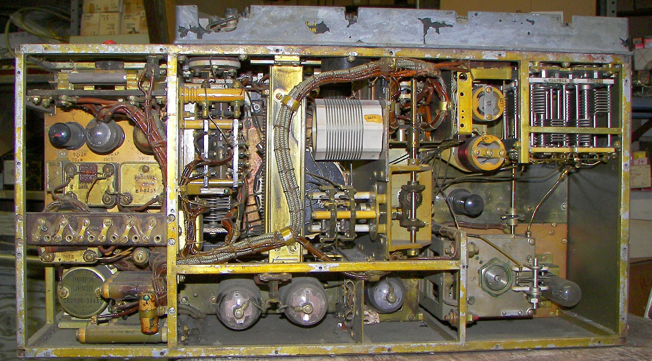
Construction:
The set weighs about 80LBs without the dynamotor, as pictured. It is a rock-solid piece of gear. The outer covers seem to be made of copper sheet. The interior is a welded rectangular tubing frame and several subchassis assemblies. Rugged switches and relays with silver-plated contacts are used throughout.
Condition:
This speciment seems 99% complete, missing only three covers and the dynamotor. Although very dirty on the outsude, with missing much paint and covered with the dusty gritty-looking remnants of packing material that has literally decayed around it, the unit is clean and in very good shape on the inside. Some silver plated items are tarnished.
Possibilities:
It would make a nice restoration for the 80M ham band, and with the right tweeking of the RF drive, could reliably do 50W carrier on AM and 200W CW.
It's a wealth of very high quality capacitors and coils, and the bandswitch could handle a legal limit linear amp easily. But I'm not stripping it. These are rare.
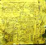
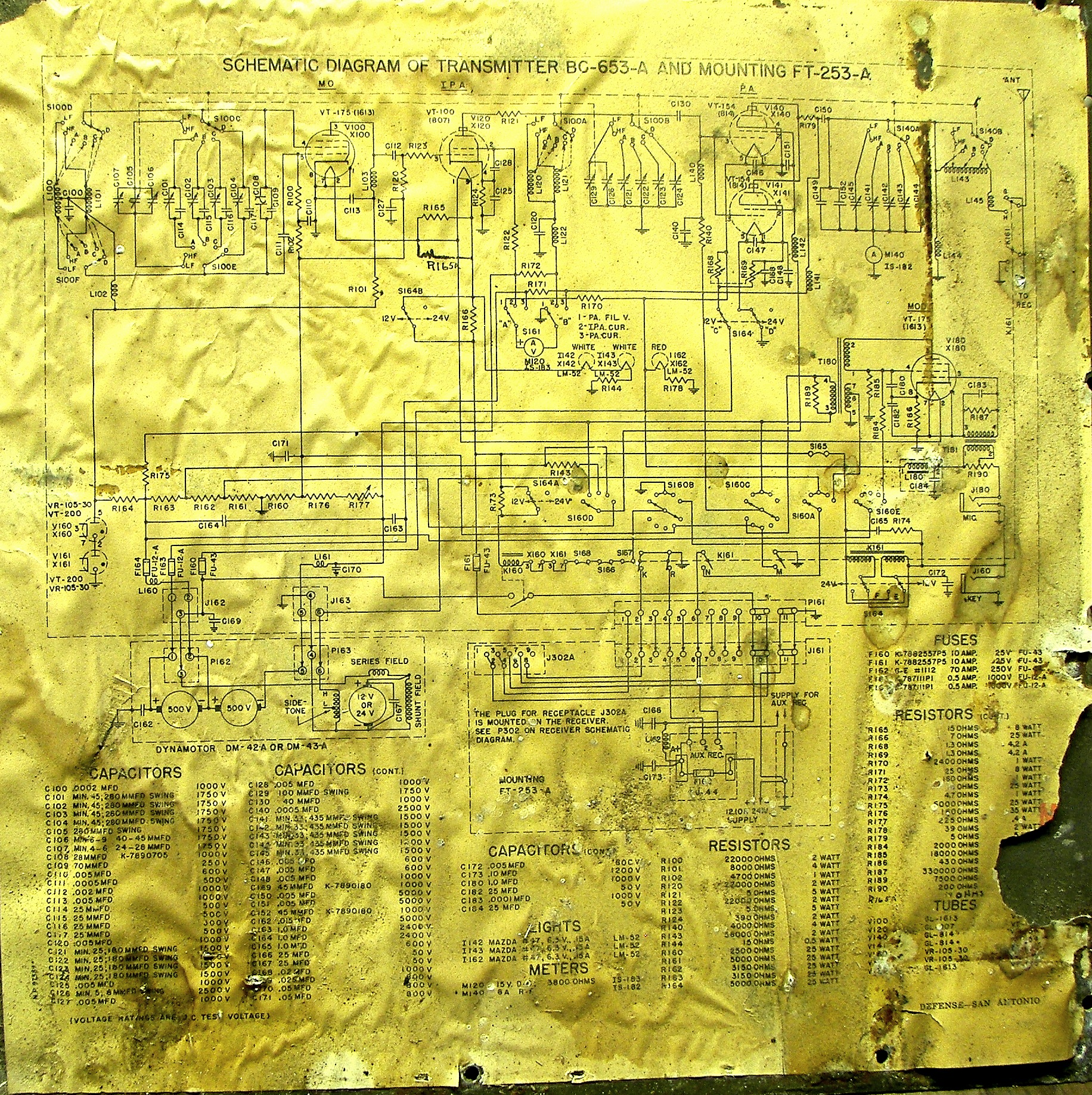
Schematic image
in PDF
N7JP version
|

as found
|
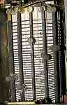
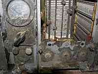
PA Tank
|
IPA tuning
|
MO tuning
|
VFO runing (lower)
|
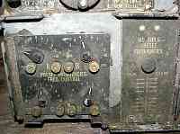
mode switch and PA coupling
|
mike and key jacks and MO preset tuning
|
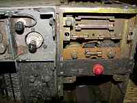
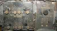
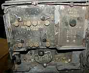
ANT and REC terminals, fuses, red lamp, PA presets
|
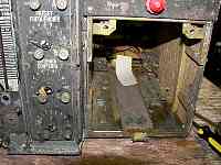
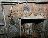
dynamotor bay, PA presets
|
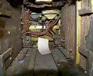
dynamotor bay
|
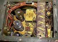
looking down into regulator and modulator section
|
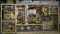
top view (different lighting)
|
top view (different lighting)
|
top view (different lighting)
|
top view (different lighting)
|

nameplate - -it IS clean on the inside!
|
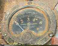
RF ammeter
|
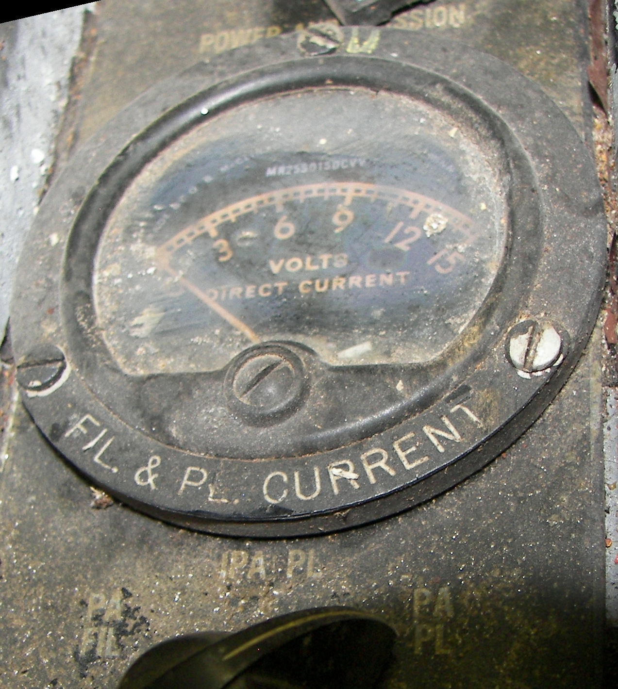
multimeter
|
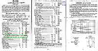
814 tube specs
|
video of still-smooth tuning operation and bandswitching
|
pic from manual, typical install. (receiver not shown)
|


