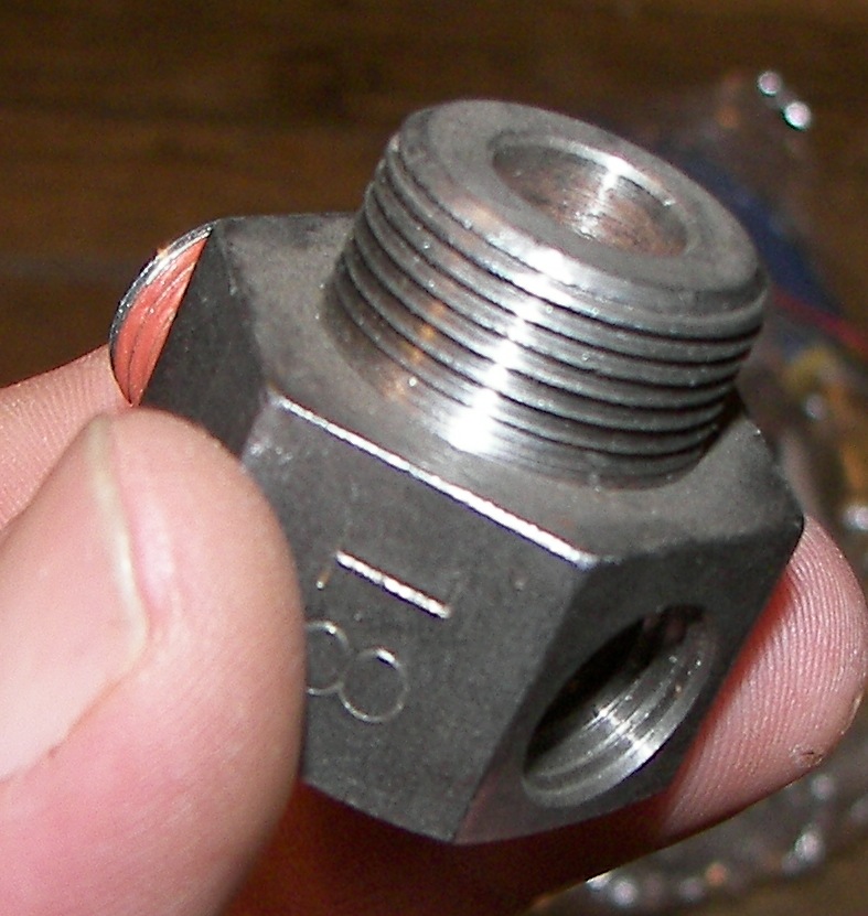
 157.61 Kb 787 x 831 The new oil pan plug. It has two holes, one for the prelube oil pickup, and one for a pipe plug for doing oil changes. The new pluf is not removed normally, since the prelube oil supply hose is connected to it. Notice the large robust size. Note the 5-ton uses a different size plug so be sure what you order. |
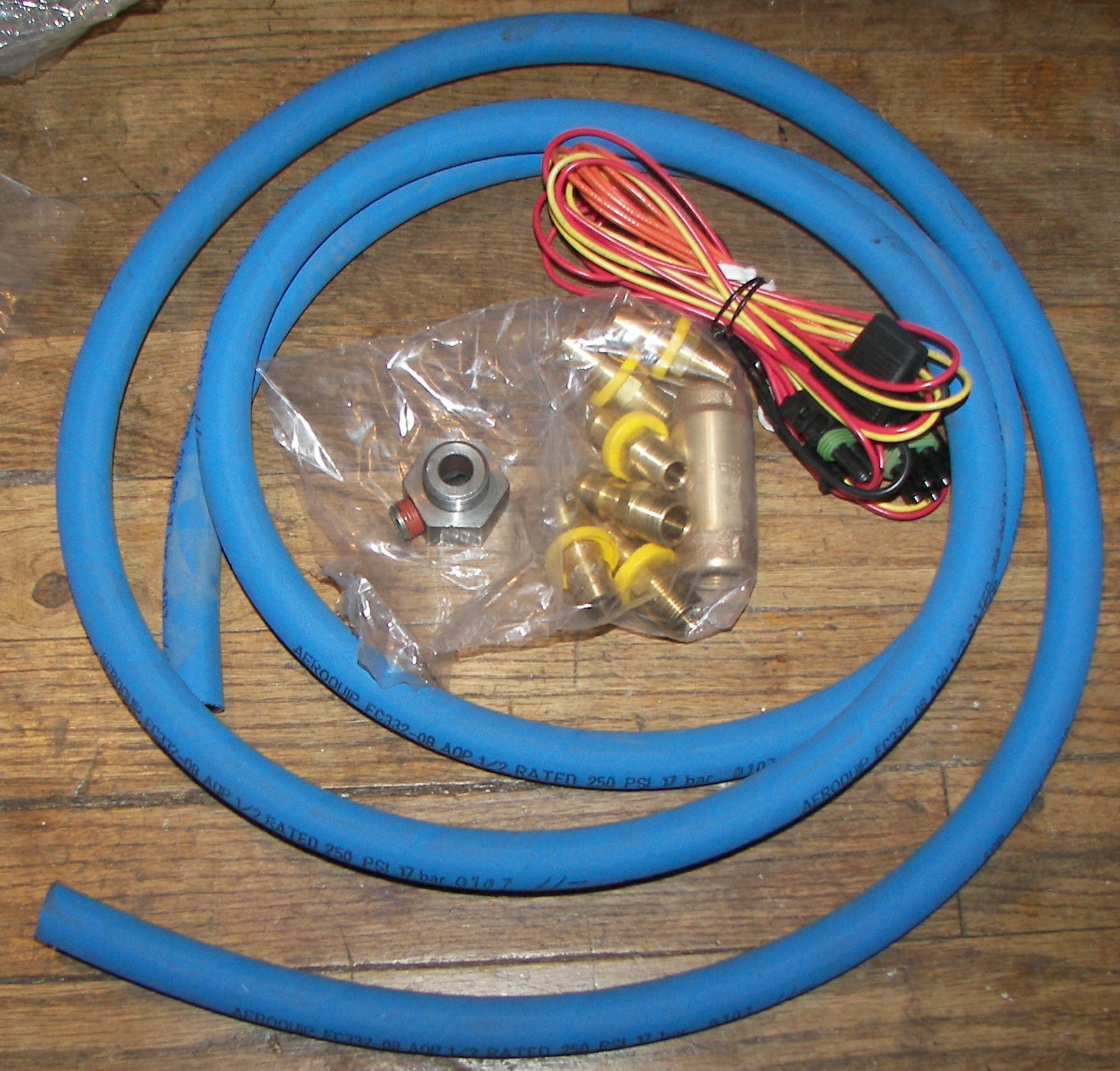 824.81 Kb 1763 x 1686 In the kit is some high pressure, high temperature hose, wiring, fittings, a check valve.. |
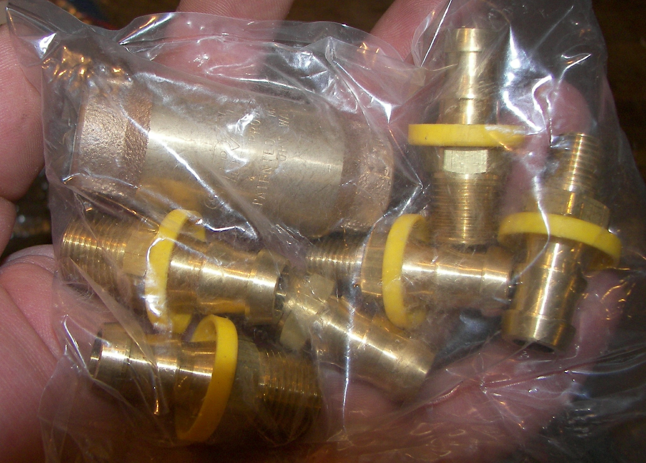 750.21 Kb 2056 x 1473 Closup of the fittings and check valve. The hose is to be pushed onto these fittings. The instructions are rather general, and despite lubing the fittings and working in warm weather with the hose, the hose was -very- difficult to push on. I didn't get it bottomed on all the fittings, but I believe it is on good enough. It's definitely not coming off! The check valve keeps the engine oil pressure from going back to the pump. Not only does this prevent any possible backflow, but is also a safety in case one of the system hoses should fail. |
 643.81 Kb 1810 x 1402 The pump of the kit. This one is 24VDC and includes a high pressure bypass valve so that once the engine starts, the pump is not pushing against the engine's own oil pressure. |
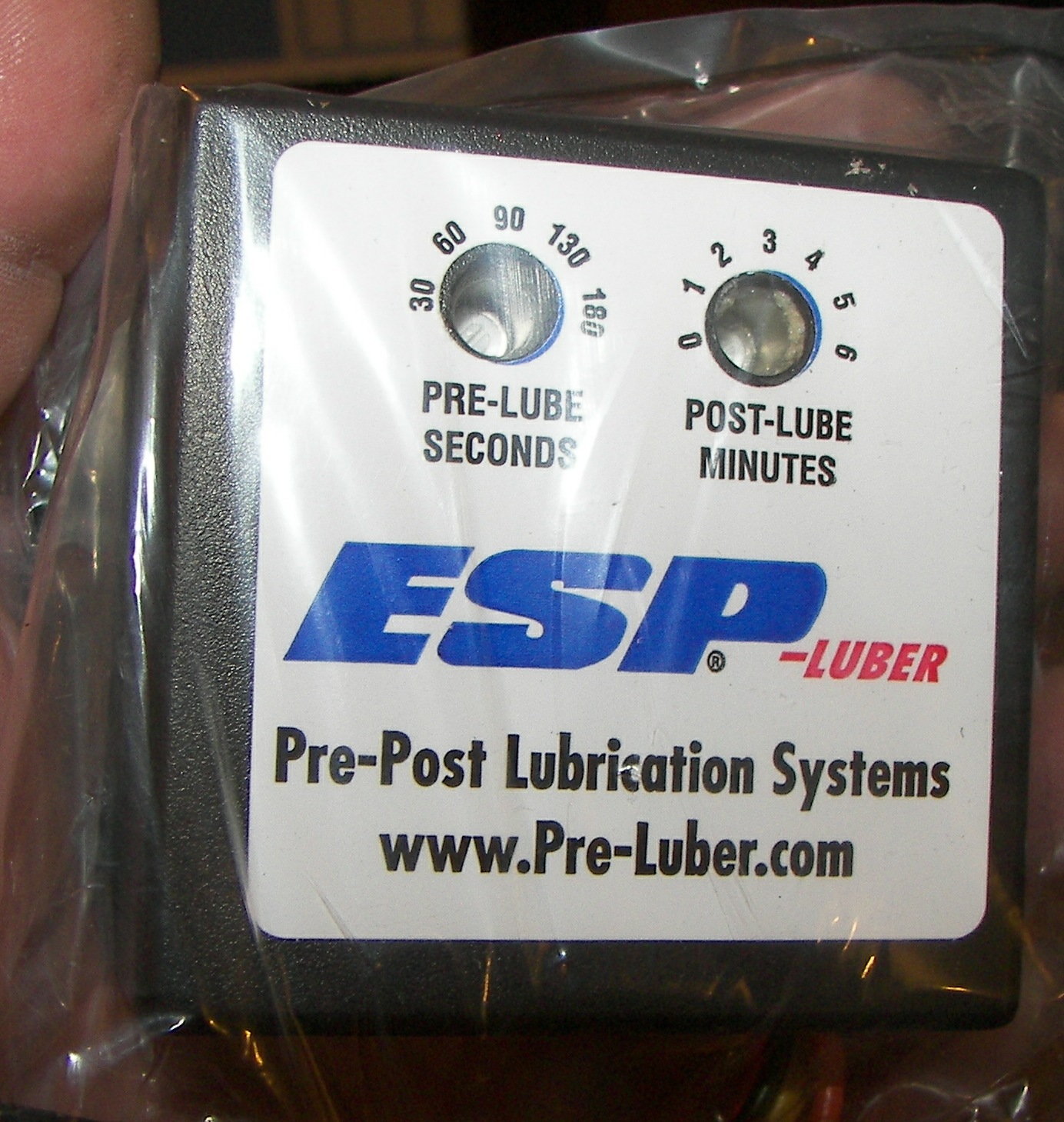 490.17 Kb 1384 x 1459 The electronic brain can be set for a prelube of up to 180 seconds and a post-lube of up to 6 minutes for those turbos. Even in vehicles without a turbo, it probably does not hurt to flow some oil through the engine's bearings for a couple minutes.. |
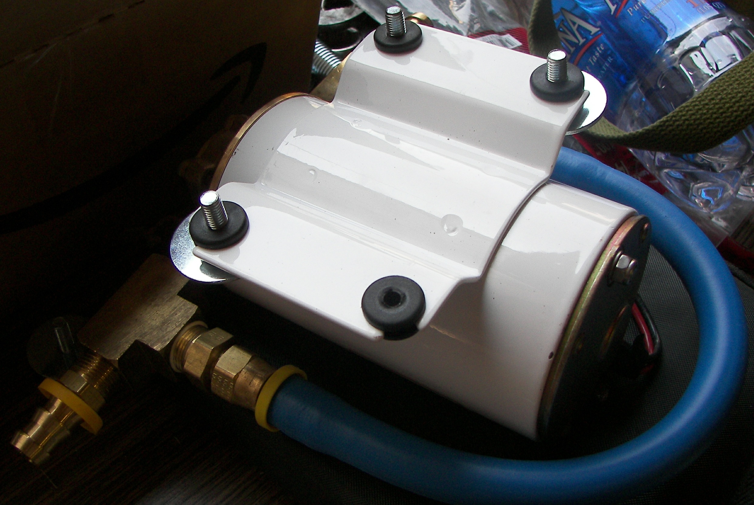 797.92 Kb 2482 x 1664 The mounting grommets on the pump are technically too small for 1/4" bolts, but they can be pushed through and will work. Note I have used fender washers to help avoid damaging the grommets. I used grade 8 fine thread fasteners. |
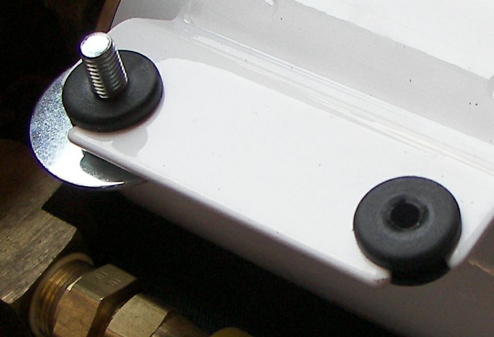 122.10 Kb 962 x 656 Close-up |
 464.08 Kb 1570 x 1131 |
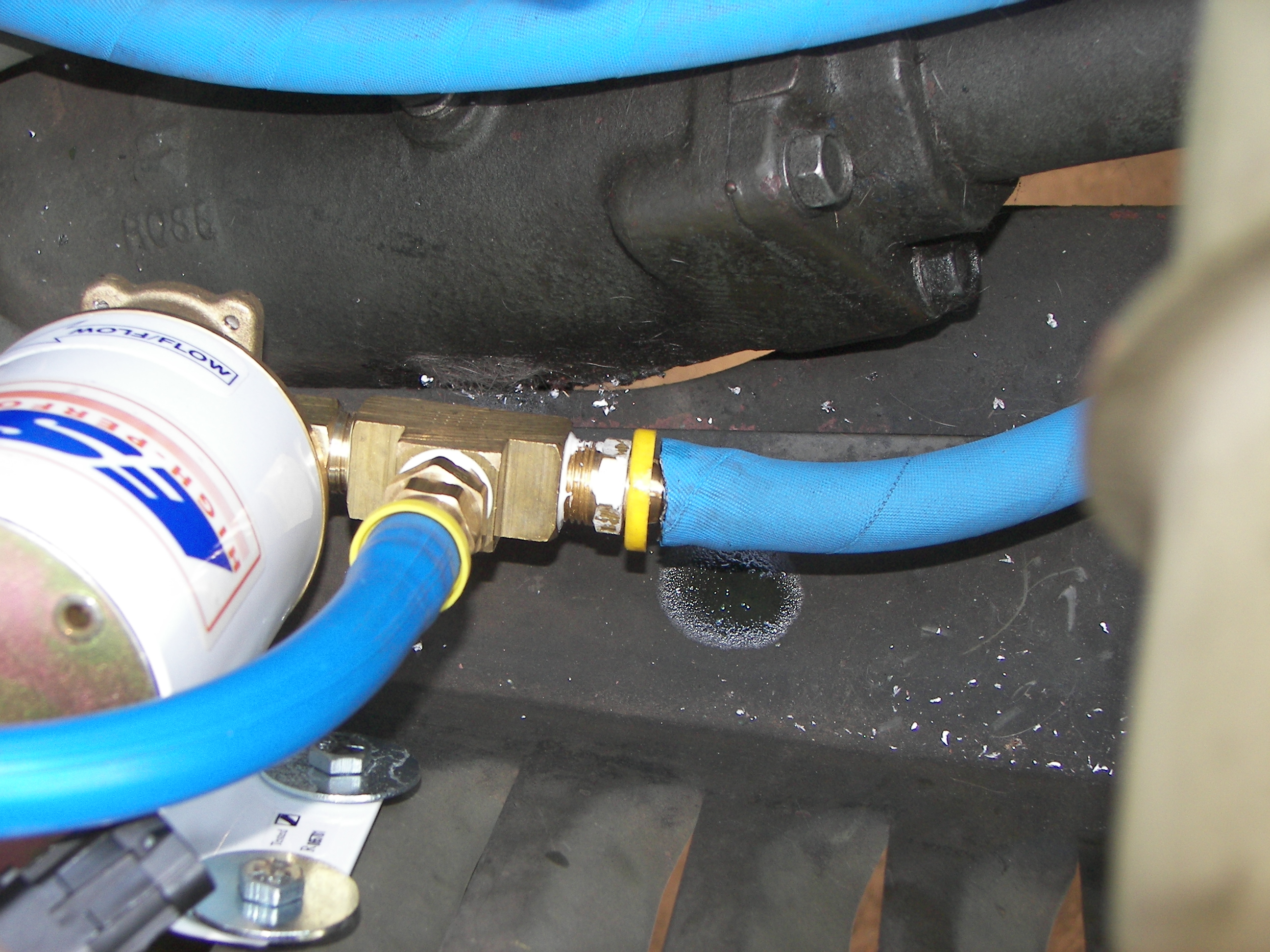
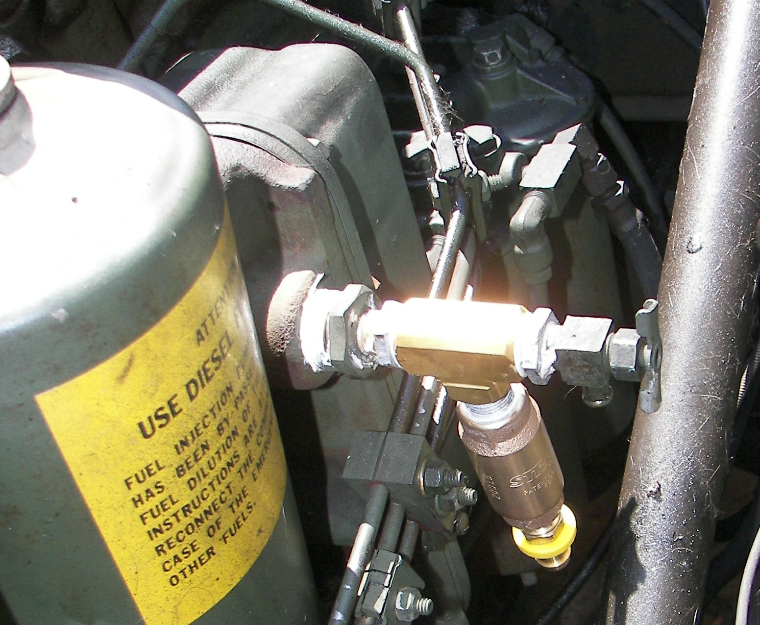 548.20 Kb 1551 x 1275 This is a bit cobbled up, since I did not have a 1/4" TEE. I used a 3/8" TEE and a 3/8" to 1/4" reducer on each end. This fits the 1/4" size of original oil sampling port via a 1/4" close nipple (NOTE: the large reducer on the oil cooler is original equipment.) and also permits the sampling valve to be retained. An issue to watch is to make sure the bottom outlet of the TEE is far out enough from the oil cooler body to avoid interference between the fuel injection lines and the check valve. |
 414.37 Kb 1140 x 1424 |
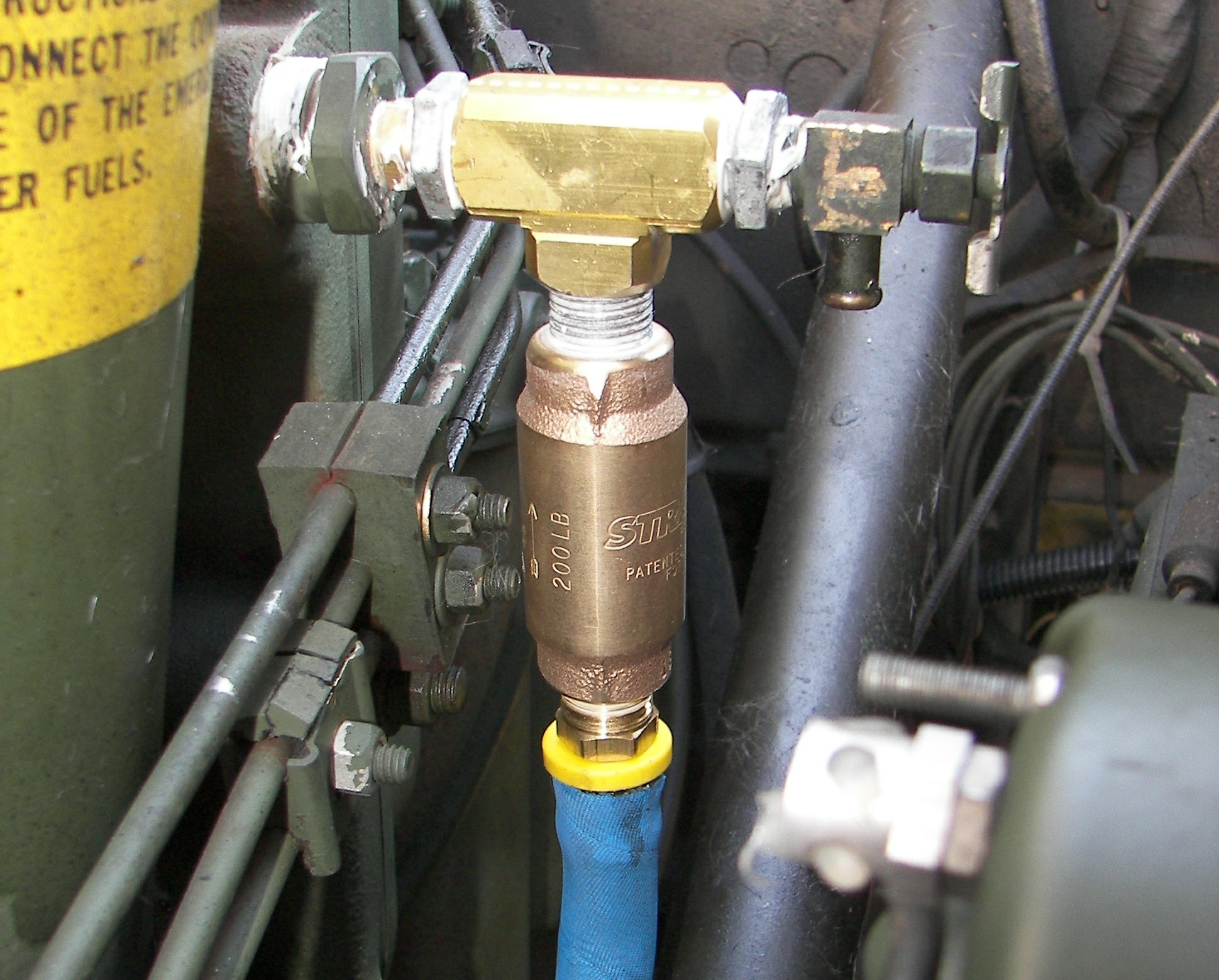
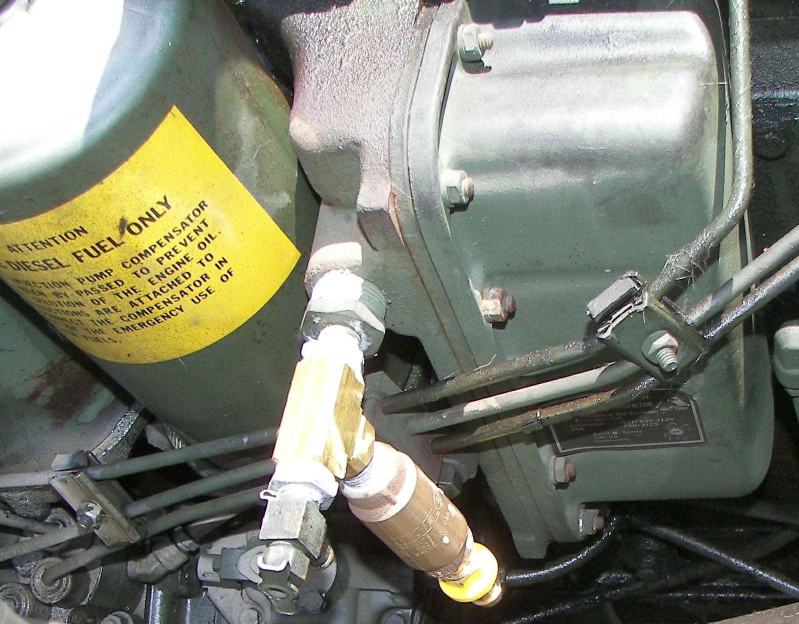 595.78 Kb 1598 x 1248 FYI the oil flow direction of the check valve is upwards to the TEE. The TEE is connected to the port which has the function "post-filter oil" |
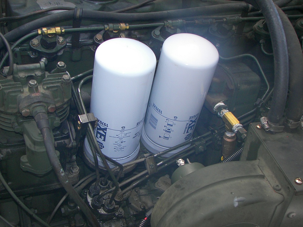
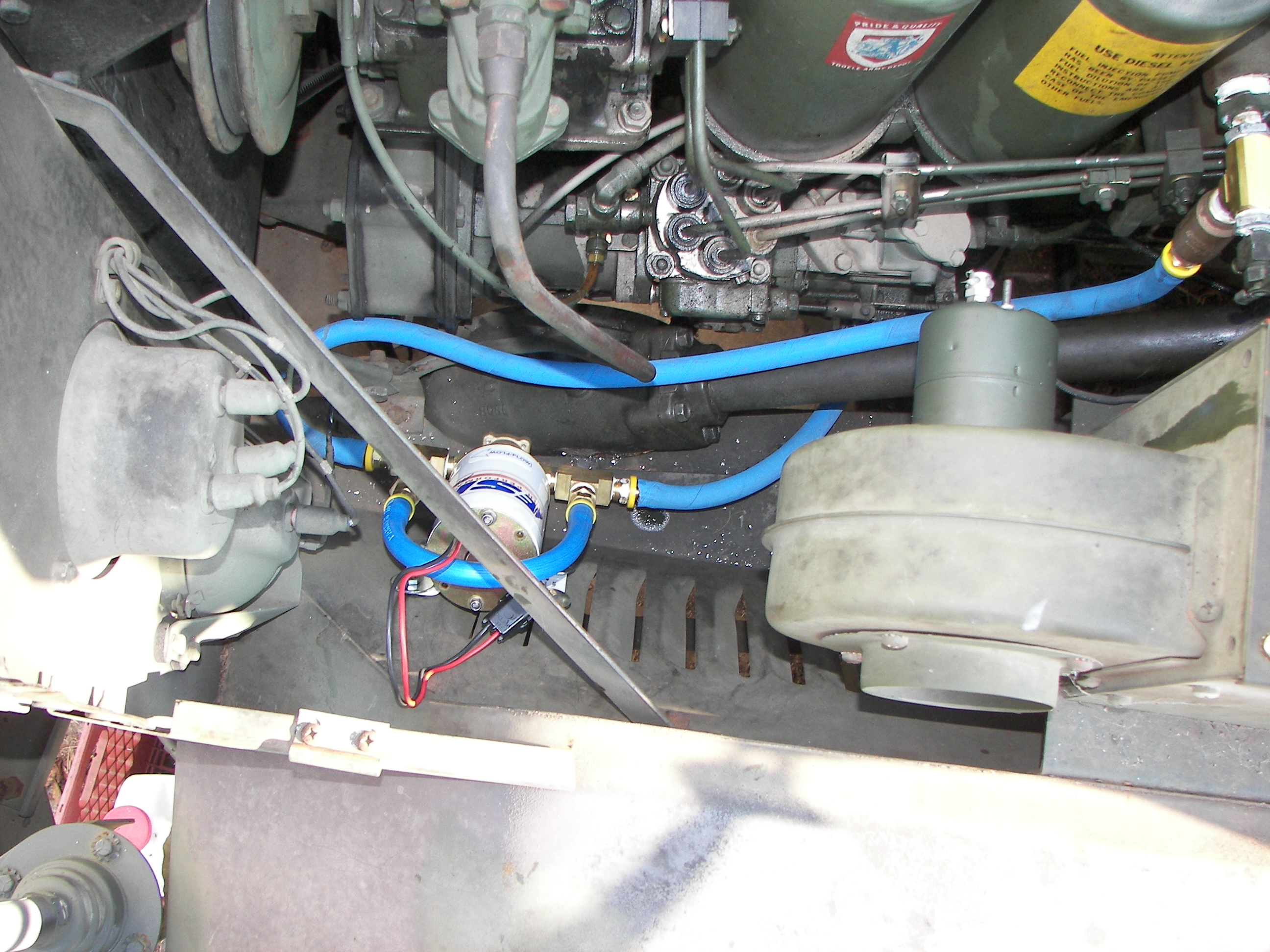
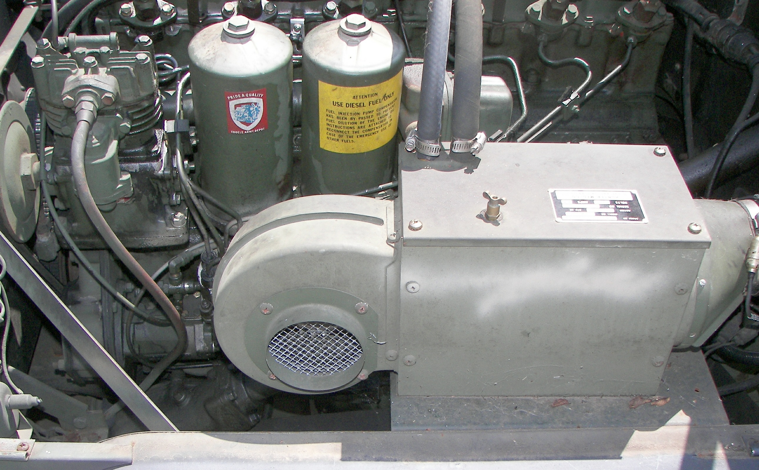 1158.85 Kb 2583 x 1600 My engine. Notice I have mounted the heater unit cloer to the firewall than usual. This lets me see the injector pump more easily for routine PMCS checks. |
 2.58 Mb 2592 x 1944 |
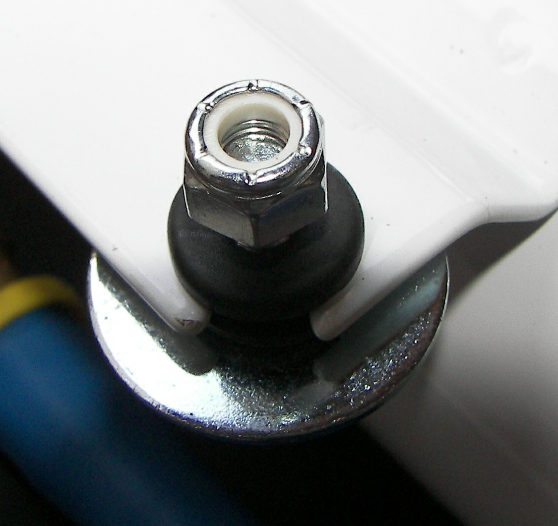 204.92 Kb 1125 x 1061 A note for mounting the lube pump. nylon-insert nuts were used so they won't back off. This was done instead of using cut-washers (lockwashers) because I did not want to crush the rubber grommets. |
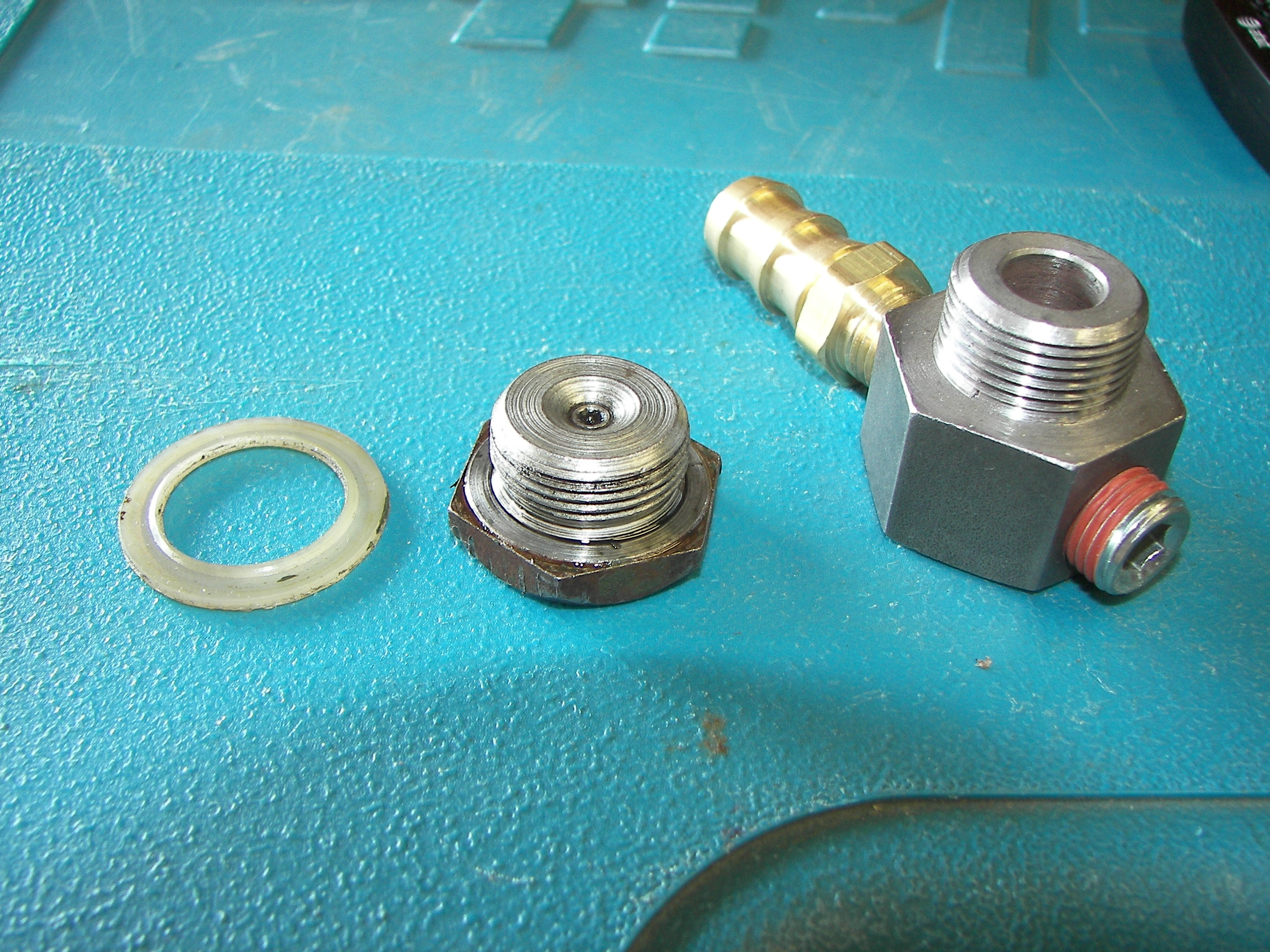 3.15 Mb 2592 x 1944 Comparison of the old oil plug, new adapter, and the nylon plug gasket. Somewhat annoyingly, the kit did not include a gasket for the new oil plug, so the old one was removed and re-used. It's tricky to get it off, but with care it can be "unscrewed" from the plug using small pliers. |
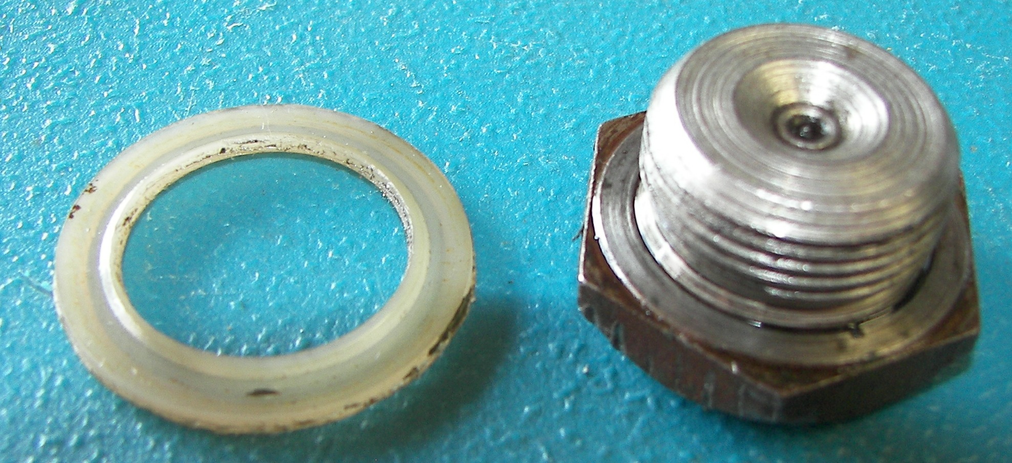 550.27 Kb 1978 x 905 The gasket has a definite direction. The side facing the oil pan has a raised lip in the center. |
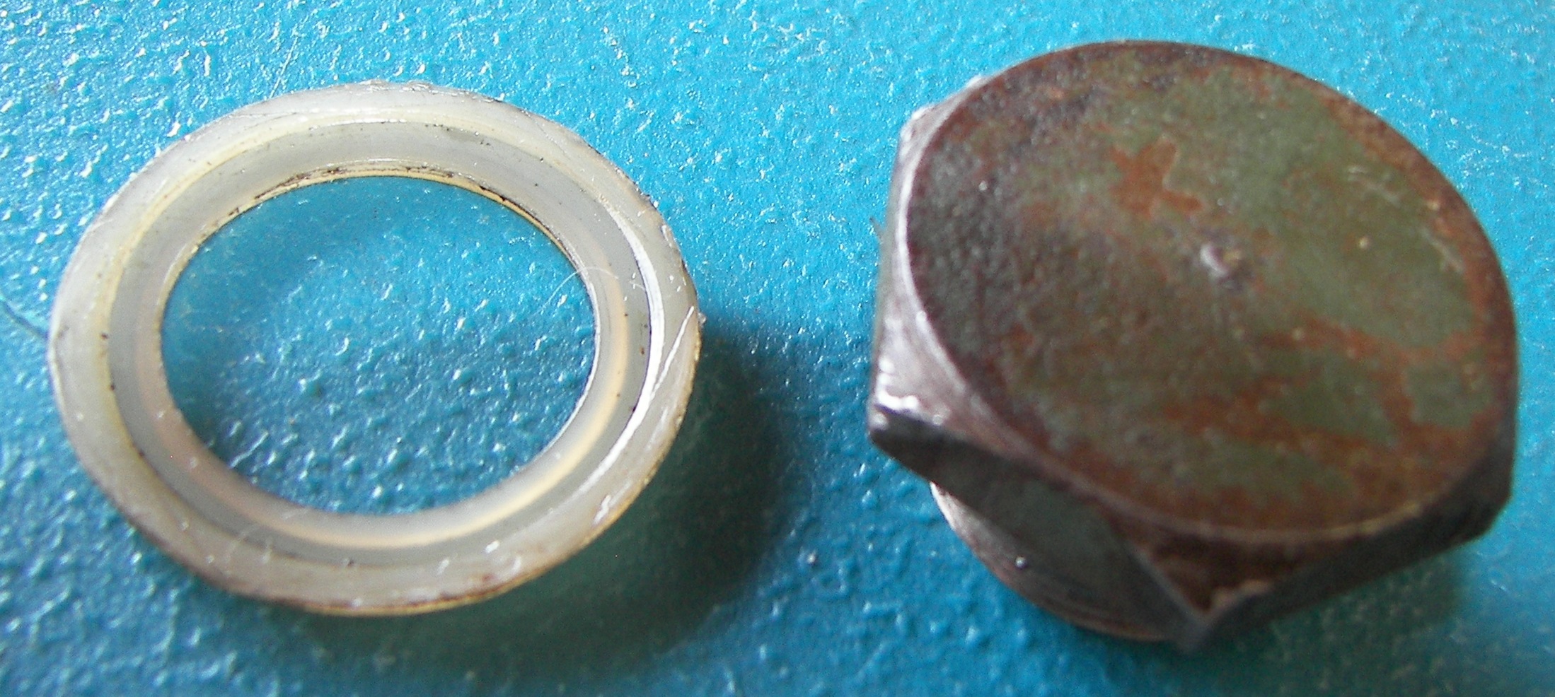 616.07 Kb 2198 x 986 The side facing the plug bolt has a depressed center. |
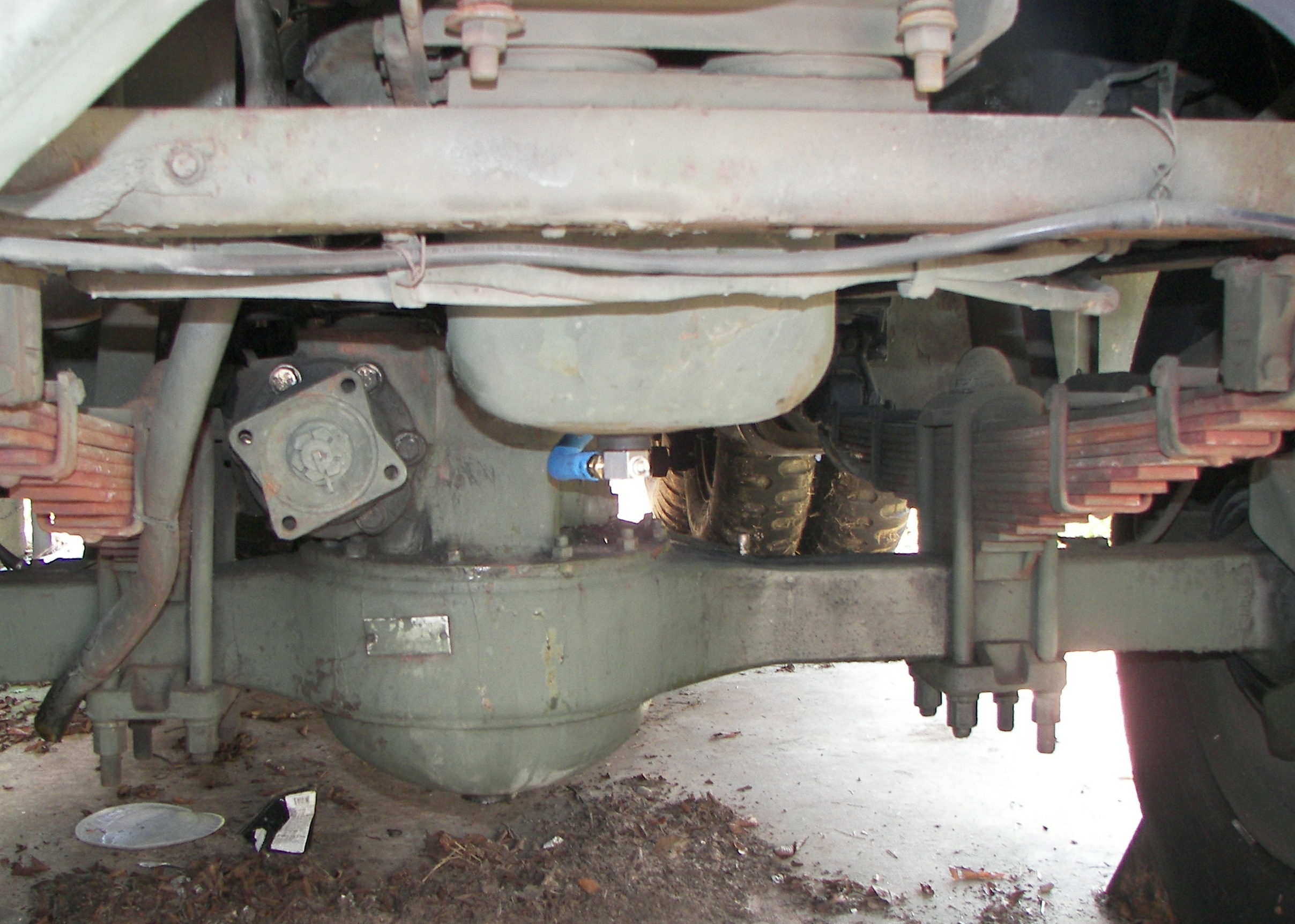
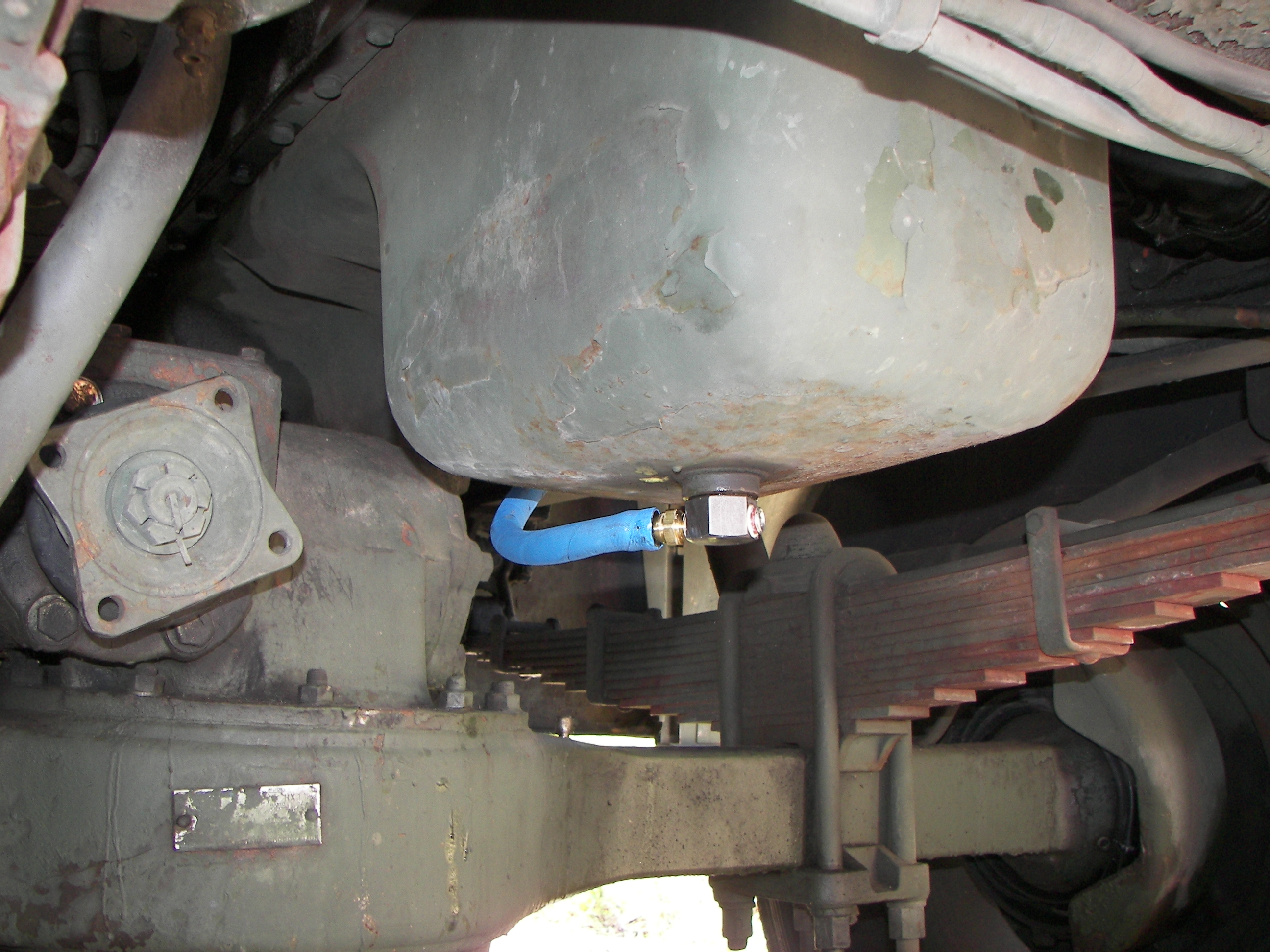 2.11 Mb 2592 x 1944 Here's that it looks like. Some folks don't like this setup because they are afraid of hitting something, but come on, look at the height above the deck. The only thing to worry about might be running over a sports car, which is not advisable in most cases. Serious off-roaders may choose to modify the oil pan to add a supply line fitting for their prelube system. I had no intention whatsoever of pulling the oil pan! This communications truck is generally not doing any rock-clinbing. |
 863.88 Kb 2416 x 1724 |
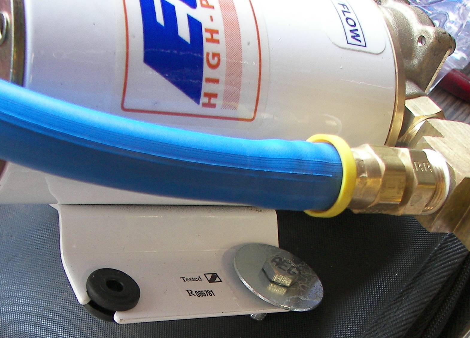
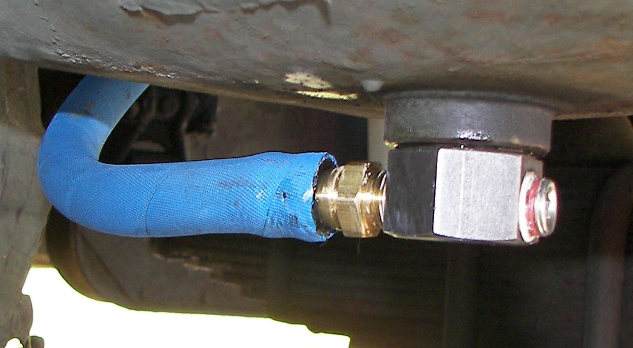
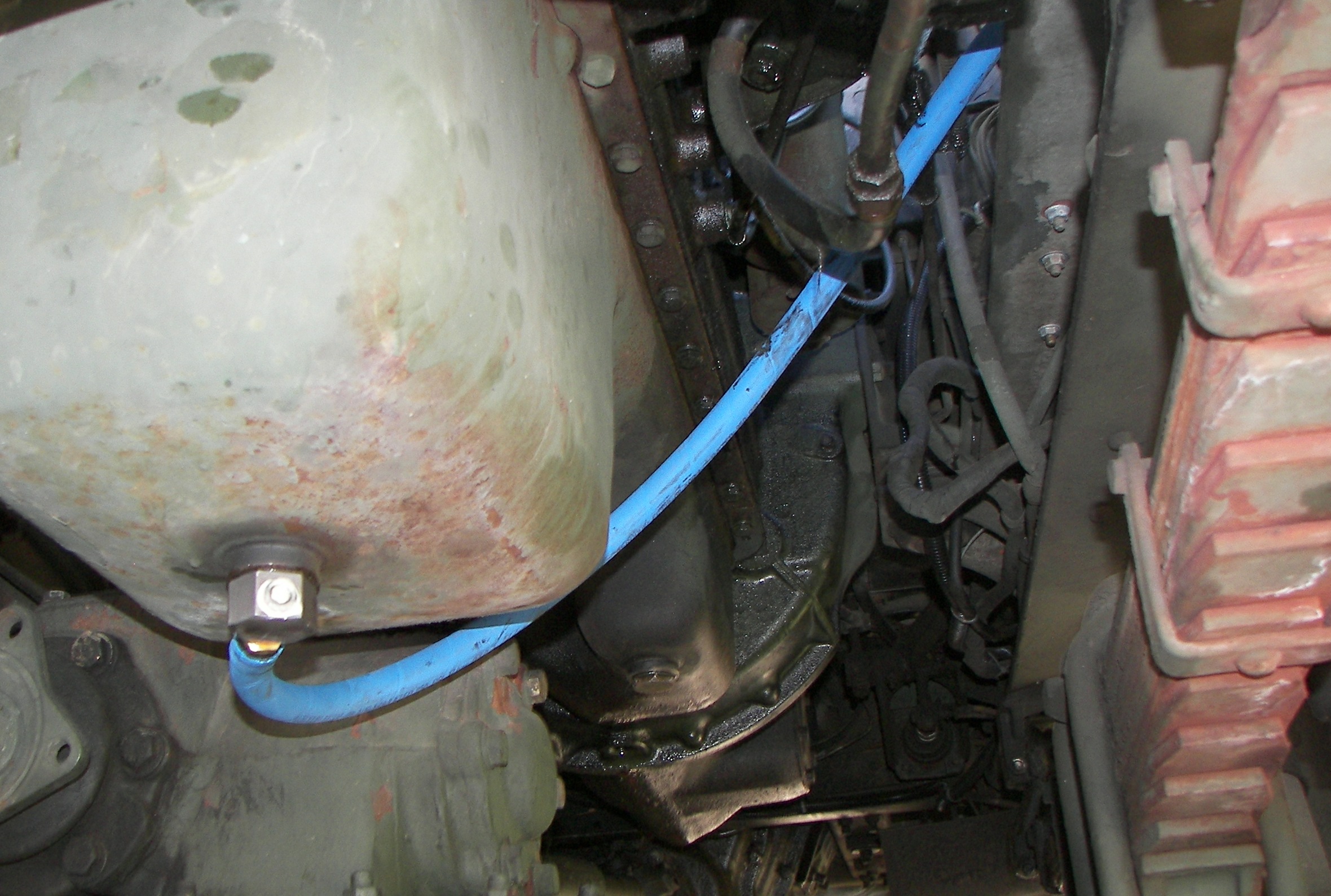 781.50 Kb 2360 x 1589 Yes I have spoken to the manufacturer about the bright "racing blue" hose.. Black is shown on the website so be sure to ask for it. It's more suitable for military vehicles. I opted to go with what was sent. It's a good, high quality hose. |
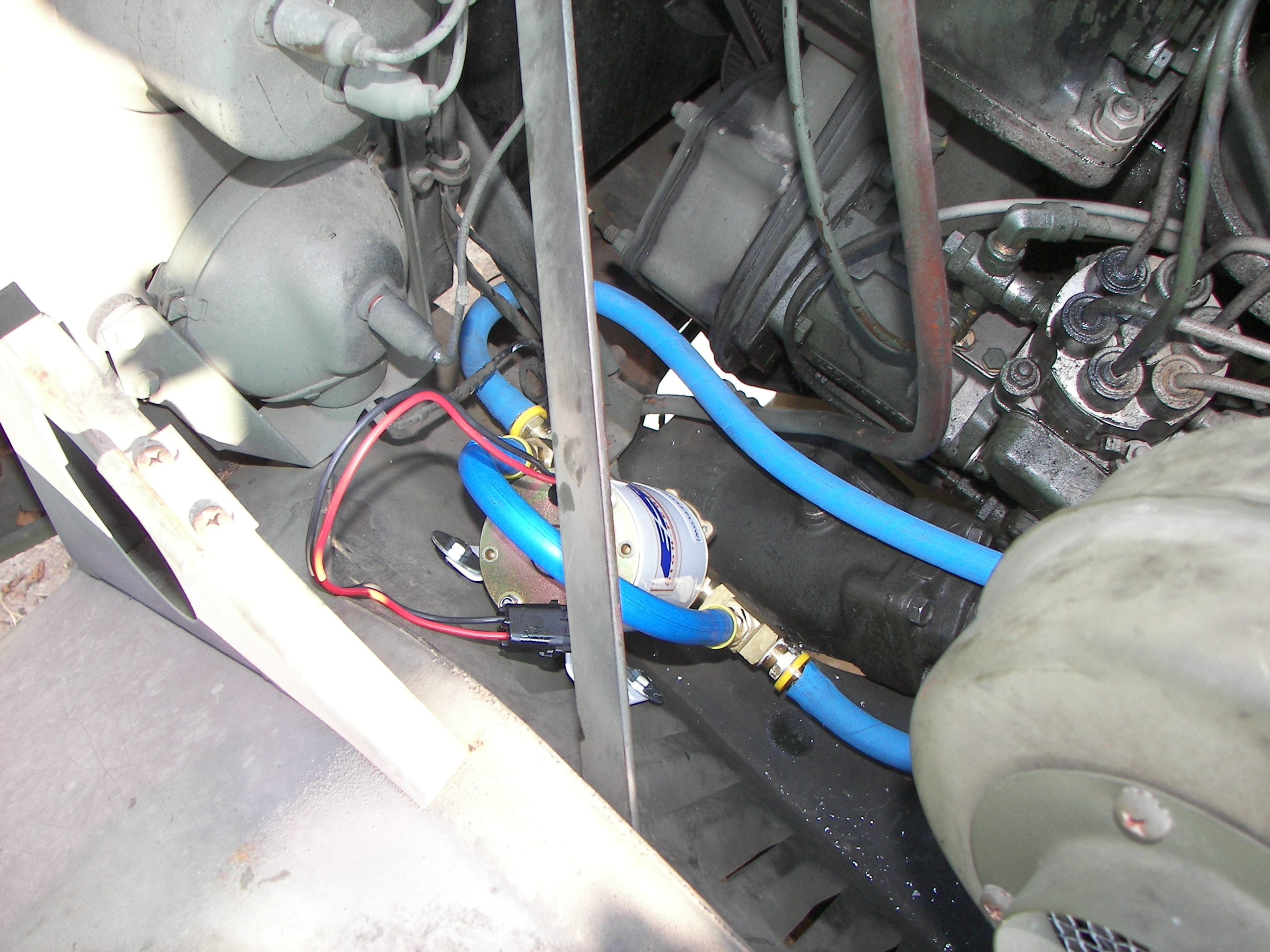 2.25 Mb 2592 x 1944 Hose routing. The direction of the pump and the required mounting angle (head down or sideways) made it necessary to loop the hose a bit. The intake is on the right, the output on the left. It would be interesting to see if a pump were available that had these reversed for the LD/LDT application. NOTE: an ideal place for the pump would have been the on side of the heater core bracket, between the bracket and the fender. I had a choice, pull the heater and bracket out and do that, or just go here on the inner fenderwell. It was 98 degrees, humid, and sunny.. so basically it ended up here. |
 2.23 Mb 2592 x 1944 I suppose I could clean up the metal chips.. The engine has a small oil leak at the front of about 1/2QT per 1000 miles, but it has not been cleaned in 4 years and the fan just blows it everywhere.. So it looks much nastier than it really is. Time for a cleanup I suppose. |
 2.30 Mb 2592 x 1944 |
 729.98 Kb 1939 x 1559 |
 145.34 Kb 974 x 580 |
 898.66 Kb 2404 x 1648 Pushing and turning and using special language, I as just unable to get the hoses pushed all the way on the but up to the fitting end. They are very very tight and I have alot of upper body strength and a crushing grip. Maybe there's a trick or tool I don't know about, but these things definitely aren't coming off anytime soon. They would have to be cut off. Once the job was done, I had about 2FT of hose left over. I may put a small hose clamp on this point just to be extra-safe. |
 196.81 Kb 1245 x 686 |