Icom IC-R9000 "bad video" CRT Display Repairs
Patrick Jankowiak KD5OEI
February 27, 2009
Home [] CRTC Video Generator Module Repair
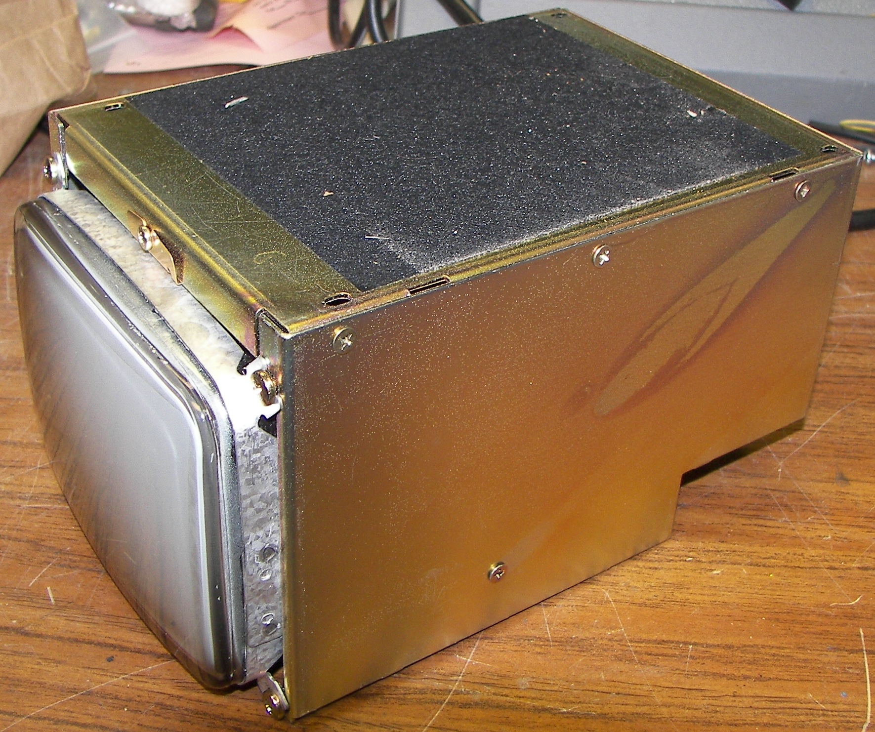
The Icom IC-R9000 has a CRT display that can give trouble. In this case the CRT had been replaced, but the display had vertical deflection problems and also had not been aligned after the CRT was replaced. The display unit's problems became evident after the repair to the video generator (CRTC board). The radio was usable but the display looked crappy, for lack of a beter term. The image lacked vertical linearity and was stretched and folded over at the top. The CRT chassis is not too difficult to remove. Do this at your own sole risk.
The most common issues for a CRT based display with vertical deflection problems will show any of these symproms:
1.) A short picture that won't evenly fill the screen from top to bottom.
2.) A picture that seems compressed or "folded over" at the top.
3.) A picture in which some items are stretched or off the screen.
There are two components that usually cause these symptoms in a CRT-based monitor.
The first is the DC blocking capacitor, usually in the return side of the deflection yoke circuit. When it loses capacitance, its resistance increases and the picture cannot go to full height. In this monitor you should be able to adjust the height so the scan area can be extended well above and below the screen area. Not that you would do that, but it needs the capability in order to function properly.
The second problem relates more to the "fold-over" symptom. There is a capacitor that is charged every trace (picture scan from top to bottom), and discharged upon retrace (the quick time during which the electron beam is returned to the top for another scan, and should be blanked out). The charge in this capacitor adds a boost to the retrace pulse to snap the beam back to the top of the screen. If this capacitor is weak, it won't hold enough charge to do the job, the beam will return slowly and become unblanked before it gets back to the top of the screen. The blanking time is fixed, and a function of the timing information embedded in the video signal, whether the monitor's sweep circuits cope with it or not.
The capacitors to replace are C407 and C410. Be sure to use caps rated for the same capacitance, 85 or 105 deg C, and low-ESR ones if possible. Using caps rated for higher voltages is also helpful. You don't want to have to take this all apart again.
While it is apart, check and resolder the connections on the components listed below the table of images. They will sometimes have cracks in the solder due to vibrations from the constant high frequency/high current deflection signals, or just from heat. In general, look for circular cracks in the solder around the pins of any component that extend through the board. Resolder them.
The monitor is out. Now to take it apart.
|
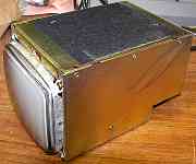
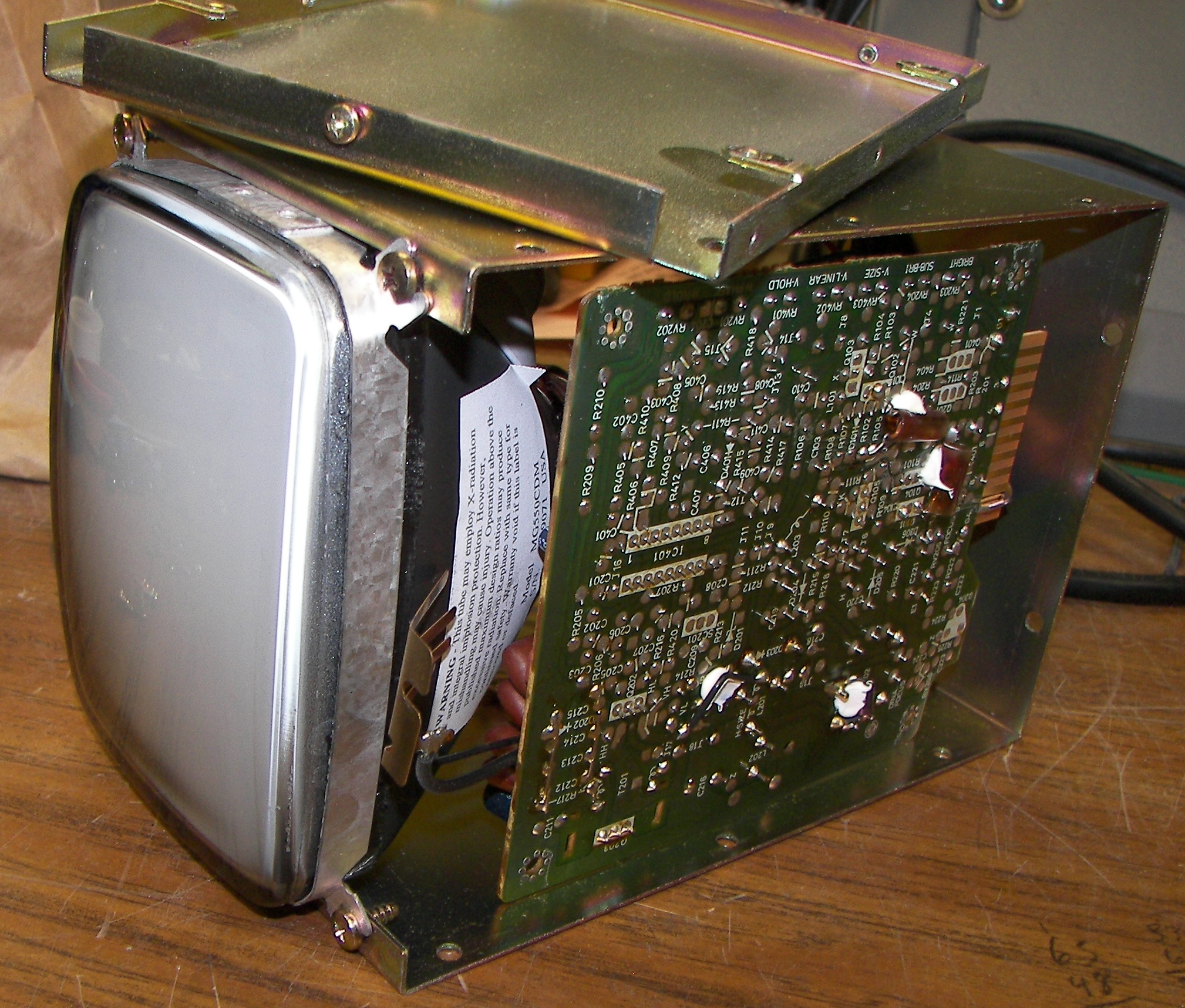
remove three screws on each side, and loosen the one at the front.
|
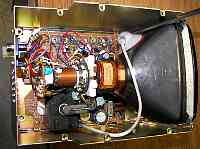
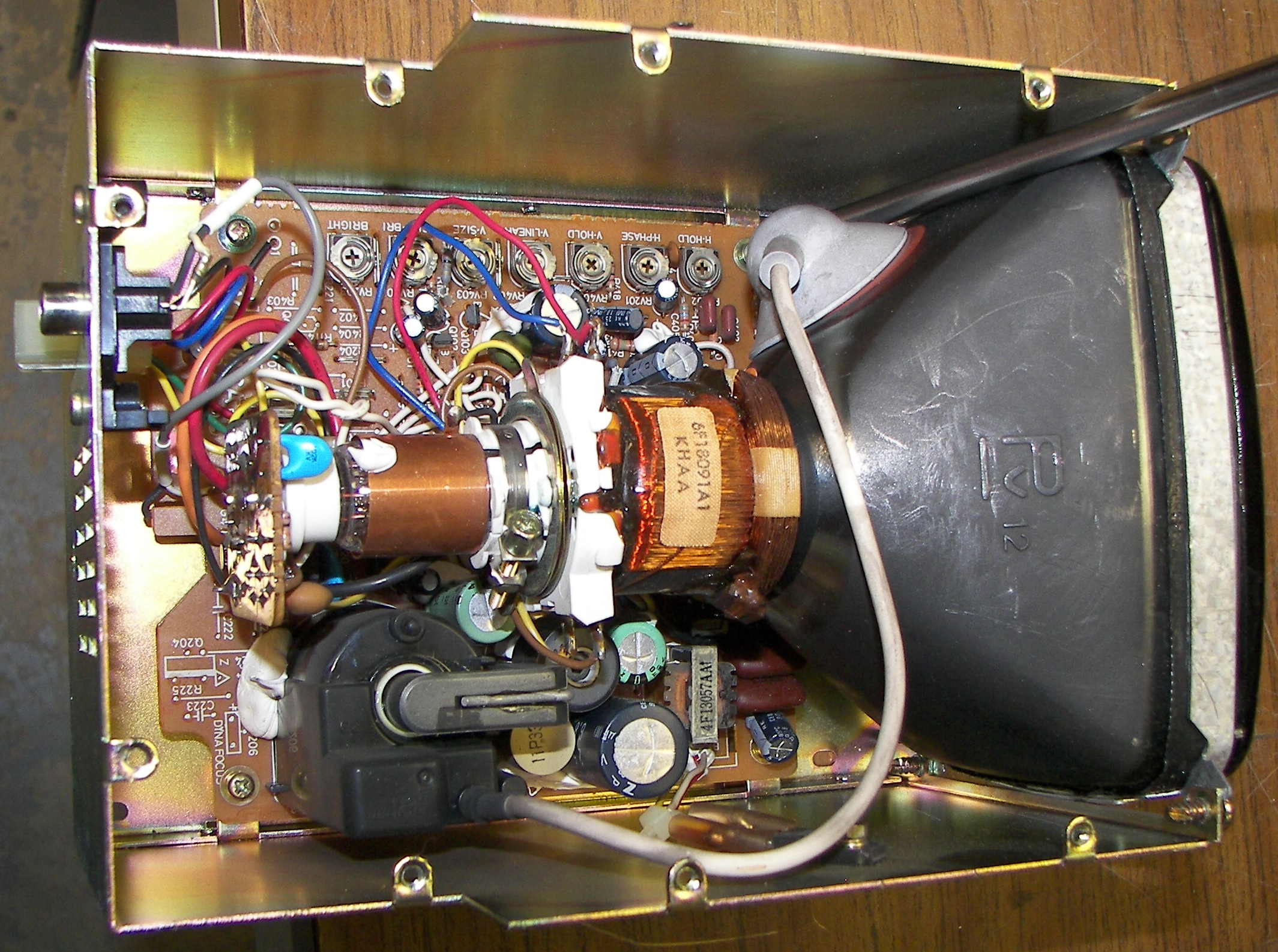
remove 4 screws at the corners of the board. Then remove the bottom plate. Note the thick wire going to the side of the CRT. This carries a high voltage of perhaps 6-8KV. Just watch it. Even after the monitor is turned off, the CRT can hold a surprising electrical charge inside this wire. If you want to check it, a probe can be slipped under the rubber cup. Be sure to use a proper high voltage probe or else.
|
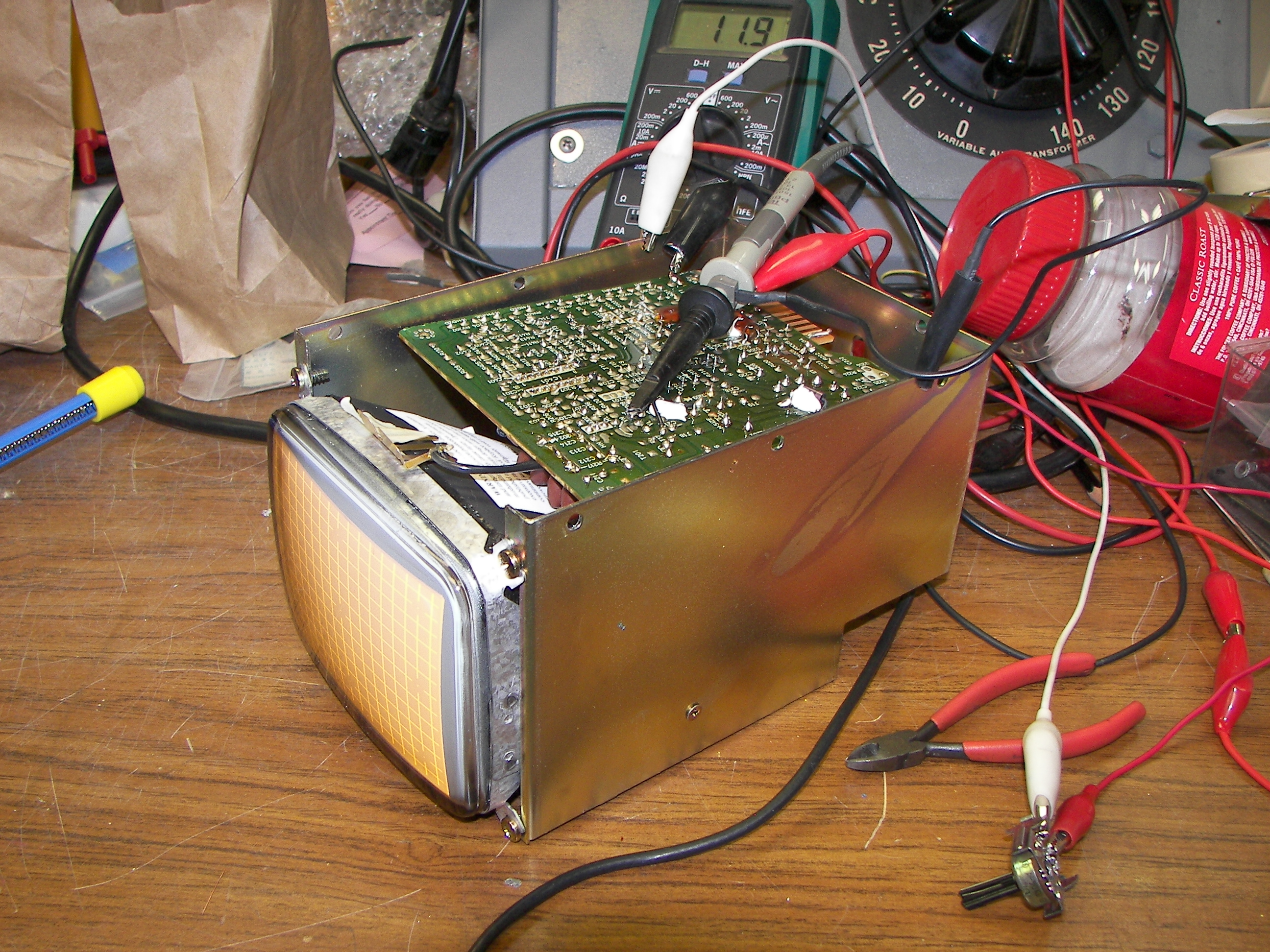
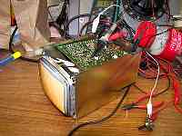
the board stays in the chassis and is easy to work on. sort of. By the way, beware the high voltage of several thousand volts. Replace the caps mentioned and resolder any bad connections. During the next steps you will power the monitor to adjust it. It takes 12 volts DC. You can do it in the radio if you wish. I did it on the bench for the first round of adjustments because I already had it powered up on the bench using a scope to verify the the bad caps and save you alot of trouble. Note under the CRT a metal set of "fingers". If working the monitor out of the radio, use a piece of masking tape to make this contact the black part of the CRT. It removes static electricity that can accumulate there. You will need a test pattern generator with crosshatch and grey scale. Best to just put it back in the radio to do the alignments unless you are familiar with this work. The radio itself has a little gray scale pattern.
|
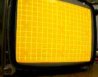
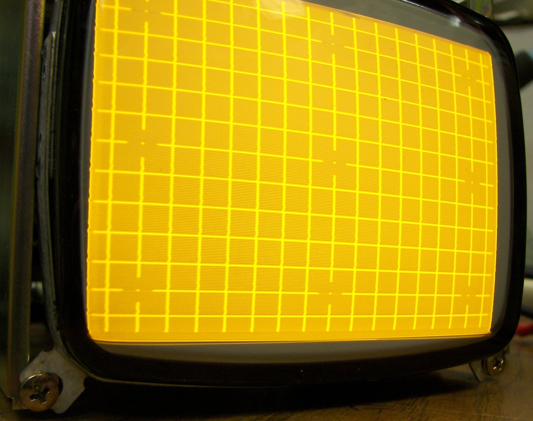
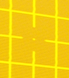
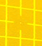
Here is a crosshatch test pattern with the brightness turned up. Notice it is nice and linear and there is niether fold-over nor retrace lines in this image because the capacitors were already replaced.
|
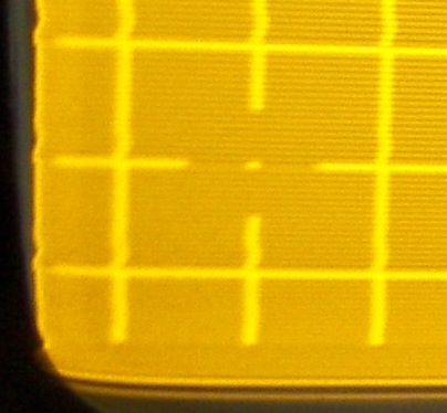
checking the focus. The center of the screen is where the focus is checked.
|
focus is not expected to be perfect in the corners.
|
notice the 50K pot there with the clip leads. This is in lieu of the brightenss control on the front of the radio. It was necessary to connect this from the monitor's power/control plug to GND to adjust the brightness on the workbench.
|
After adjusting the sub-brightness. Center the chassis brightness pot and set the sub-brightness for this appearance.
|
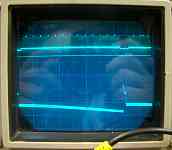
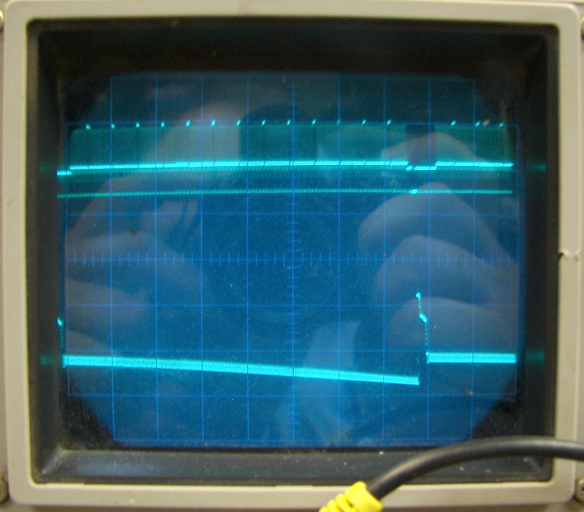
Comparing the crosshatch video signal with the high side of the vertical deflection yoke voltage. This is the proper appearance of the vertical deflection yoke voltage. When it was 'bad', the big pulse there was shorter, triangular, and very skinny.
|
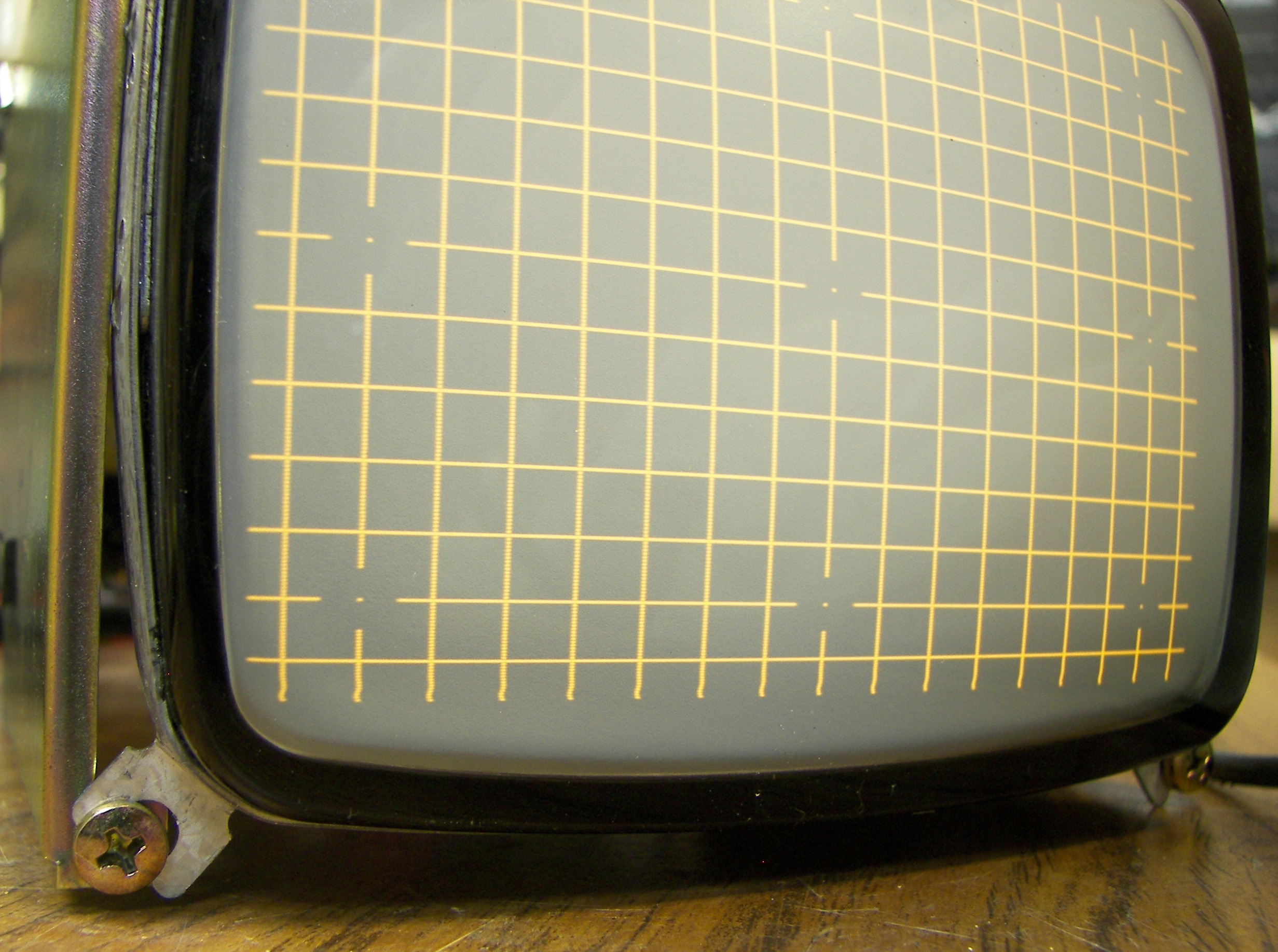
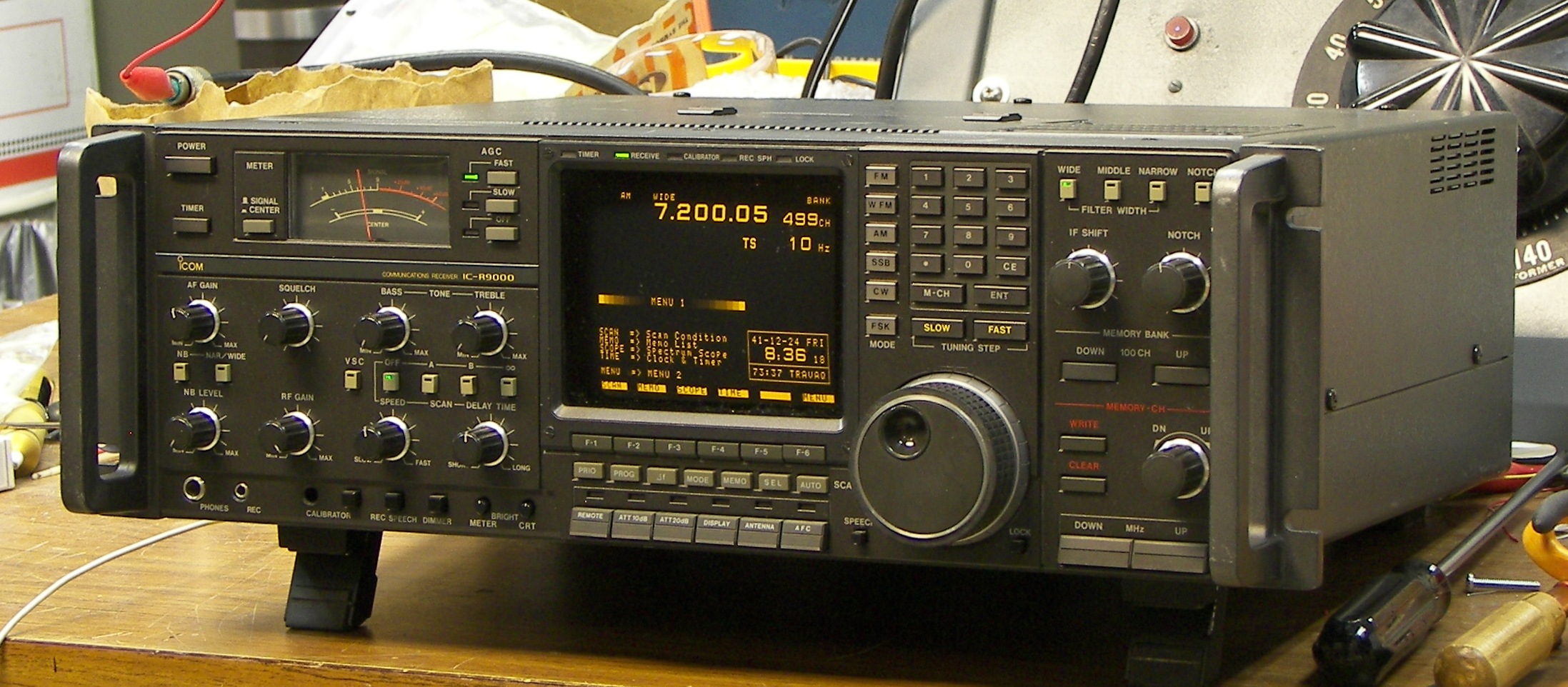
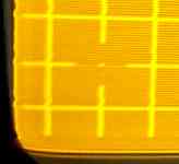
Finally done. This is what it should look like. Note the fading blocks surrounding the MENU label on the CRT's image. This is the built-in gray scale. It can be used to set the brightness and contrast. The tips for doing this and more are below.
|
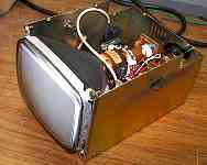
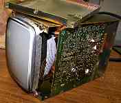
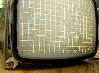
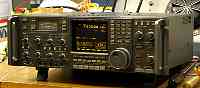
For reference, the picture shows how to remove the CRT unit.
|
Components to resolder (where leads pass through board):
T201
L201
L202
D205
D206
Q202
Q203
IC401
L203
Q105
D401
To do the following steps, use the owners manual for guidance on operating the radio and connecting signals to it.
setting the geometry, width, and centering:
increase the brightness and make sure the screen display is completely included in the scanned area and not chopped off or right against the edge of the scan. Use the H Phase control to adjust. Then set the brightness back to normal.
use a video signal generator with a crosshatch and feed it into the video in jack on the back of the radio. Press the display buttion to switch to this.
size the image horizontally using a diddle stick in the width coil so that the outer blocks of hatch are nearly off the screen.
size the image vertically using the CRT chassis V height and V lin controls. All the boxes should be the same size from top to bottom and the outer blocks of hatch are nearly off the screen.
adjust the centering by moving the magnetic rings with the tabs that are at the back of the deflection yoke. It takes some fiddling. Be sure to look at the display straight-on so you do not make a parallax error. The center vertical line of the crosshatch will point down to the intersection of the F3 and F4 buttons. The crosshatch will have the same amount of its outer boxes off the screen, all the way around.
go back and adjust H width and V height again to tweek.
press the display button again to go back to the radio's menu. See that the F3 and F4 icons are centered abov the F3 and F4 buttons. Some adjustment of width will help the F1 and F6 icons to be placed over the F1 and F6 buttons. It may not be perfect, as the Horizontal linearity can change wien the width is expanded too much, and this monitor has no adjustment for that. A week of the H Phase control can help.
connect VHF antenna and tune in a TV program. Press the display button so the TV picture is shown. It won't be very bright. it's not supposed to be. Make sure it looks good and fills the screen completely, just like any cheap black and white TV.
Setting the brightness and contrast:
Set the front panel brightness to half, dimmer OFF
set the CRT chassis brightness to half.
set the CRT chassis sub-brightness so that the background of the screen is just barely visible (the black area very fainly glows), then back off the CRT chassis sub-brightness so you cannot see the background, barely. Use your hand to keep room light off the screen to best judge this.
set the CRT chassis contrast control so that the bright parts of the pictue such as the menu button designations are as bright as possible without losing sharpness or focus. It will be worse at the corners.
check the focus at the center. If it is good, no need to adjust the CRT chassis focus control again.
Having done this, it will be very close. Now, using the gray scale blocks on the display as shown, tweek the CRT chassis brightness and contrast so that the brightest block remains as bright as possible while sharply focused, and the dimmest block is barely visible.
done!
If any part of this is unclear, consult an electronics expert. I disclaim liability for everything from the beginning of time until the end of time.
Patrick Jankowiak KD5OEI