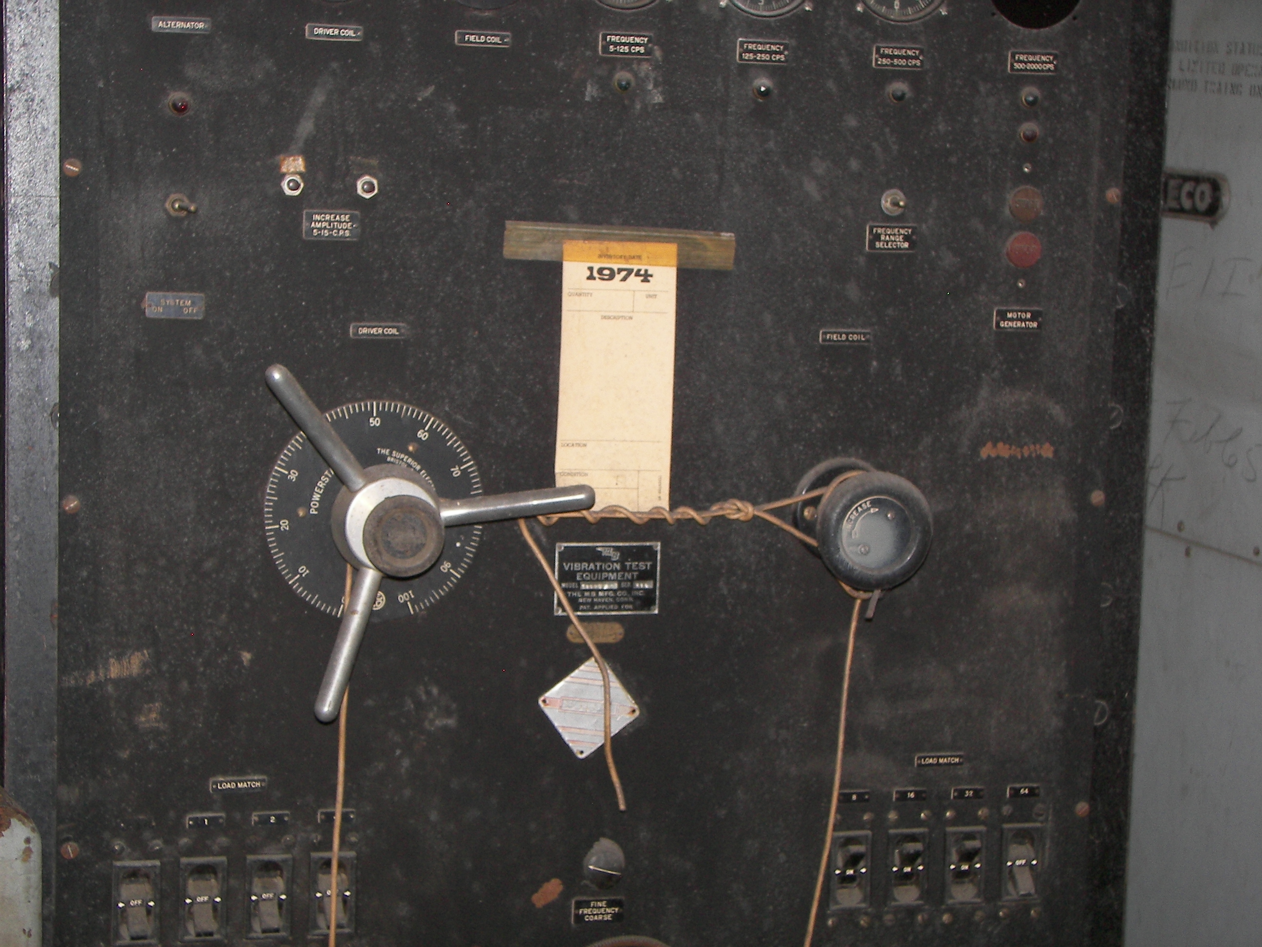
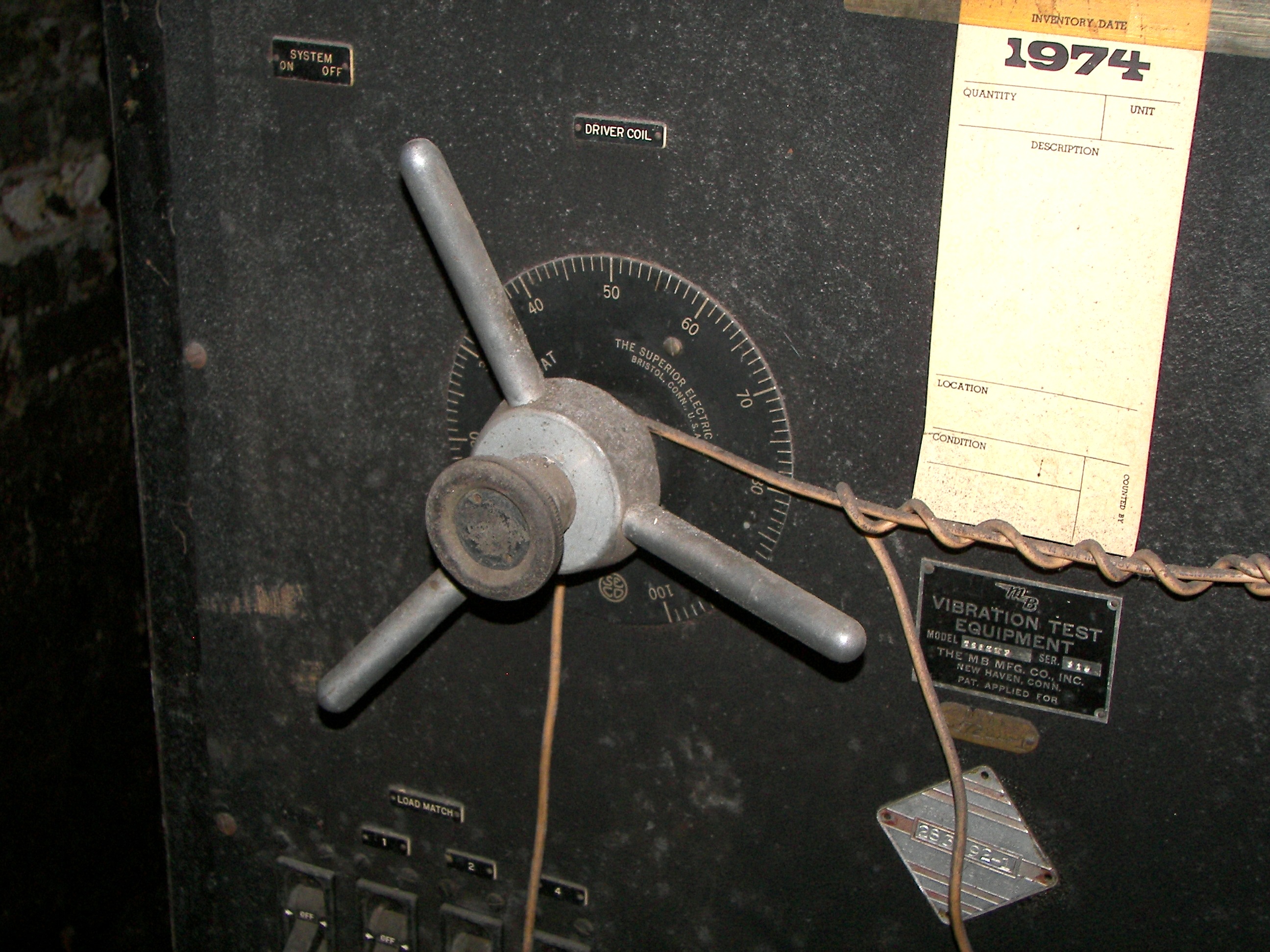
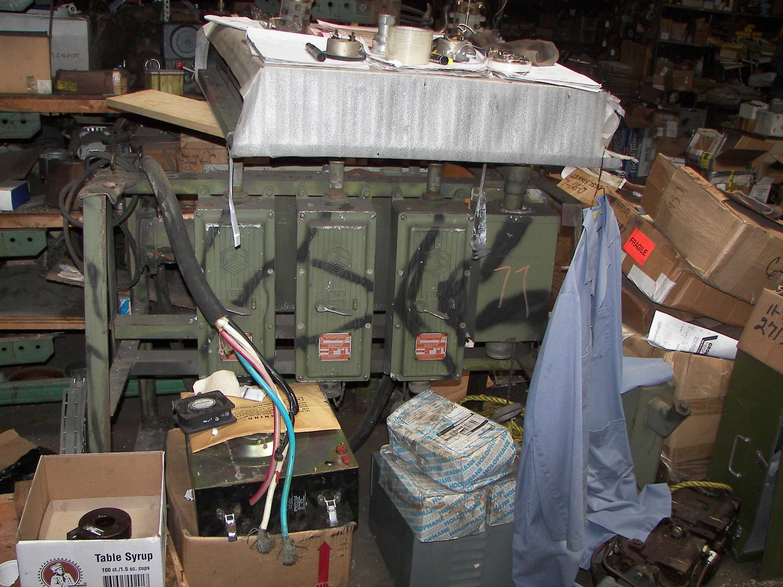
The big lever goes to the big variacs!
looks like a pump-actuated cylinder of some kind. There are several.
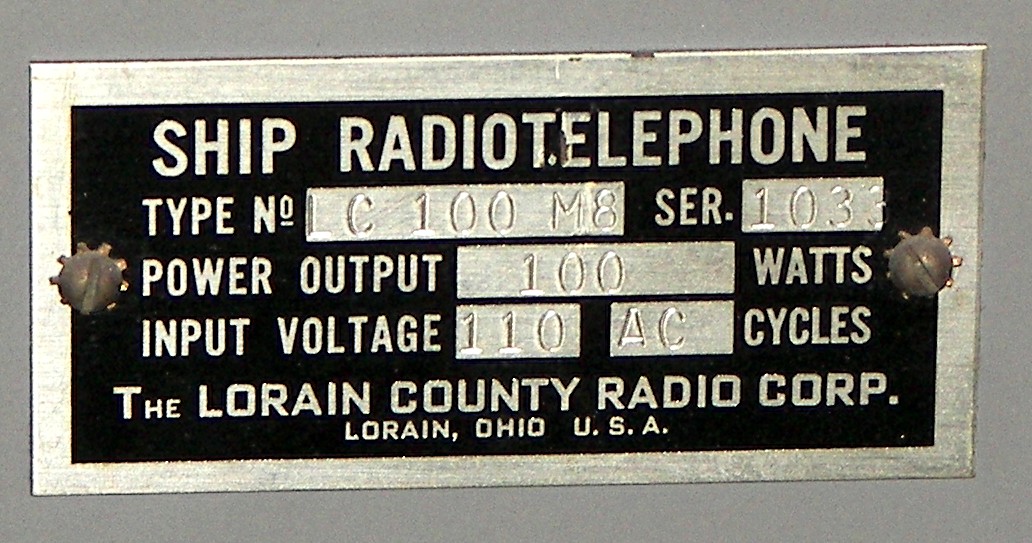
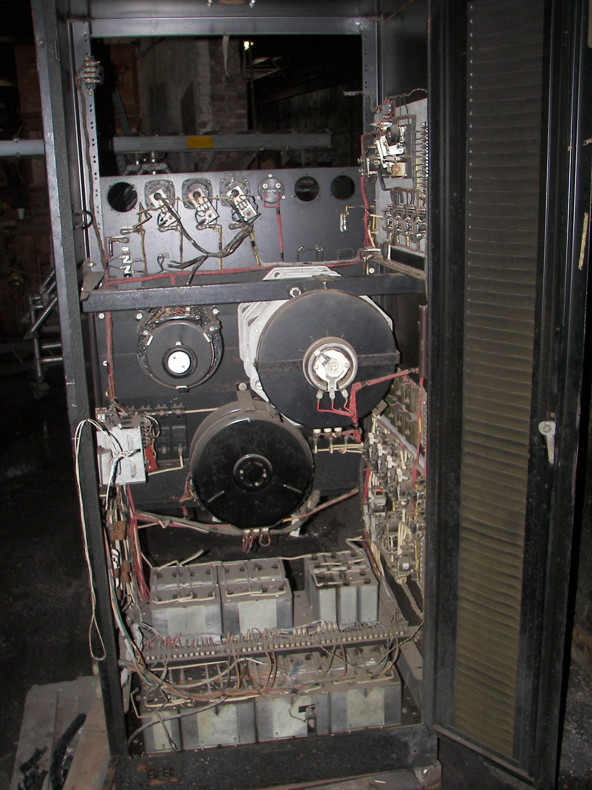
remaining photos are of the Loraine radio transmitter, type LC 100 M8. This isna 100 watt AM tranceiver with eight selectable channels. A crystal and apparently a separate RF front end (drawer) is used for each channel, and tuning is pre-set by the technician so that the operator need only turn the switch and select the desired channel. Final appears to be one or two 4D32's (could not see in the back) and modulators appear to be 807's. Unit seems to be complete. A couple ceramic standoffs are broken but that won't stop anyine from getting it fixed up and on the air. It is fairly clean inside as can be seen, someone should collect this, it's been sitting in there for many years, somewhat hidden and I uncovered it on my visit. There was a similar but smaller unit there, and I bought it. I would have taken both but only had room in the truck for the smaller one. Unit is ex-coast guard. It would be a great rig for those AM ham radio sessions.
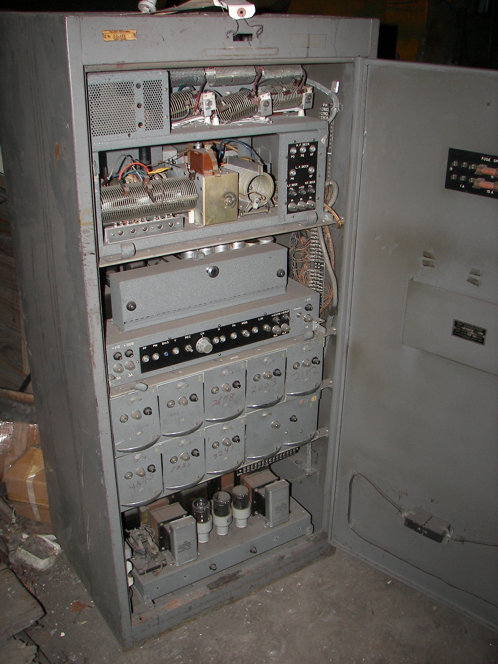
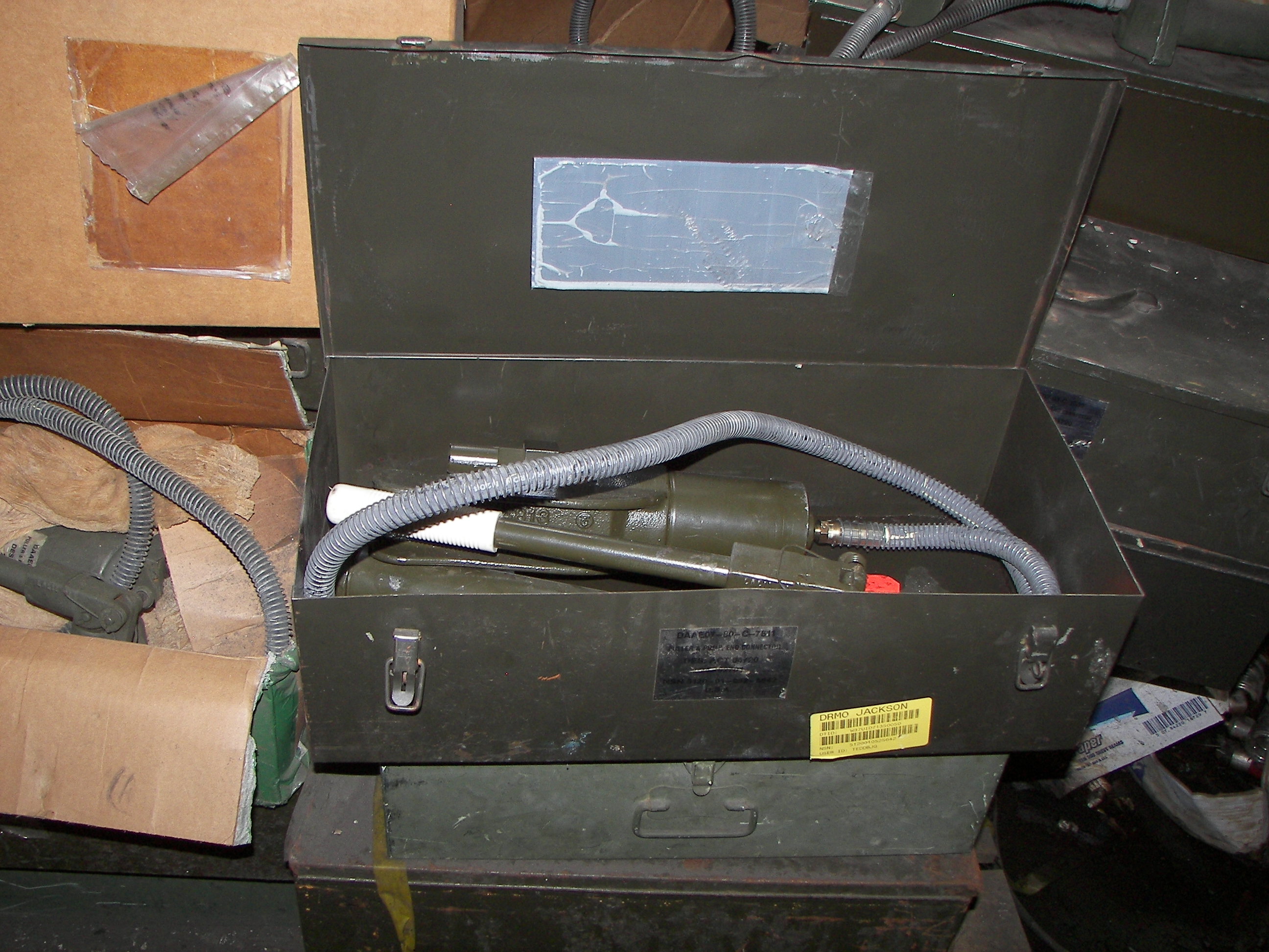
Note the extension cable for use when servicing the channel units. The only thing missing is the manual, but the devout enthusiast won't absolutely -need- that. The little drawer with the chrome knob encloses the relays, seem to be for selecting the channel.

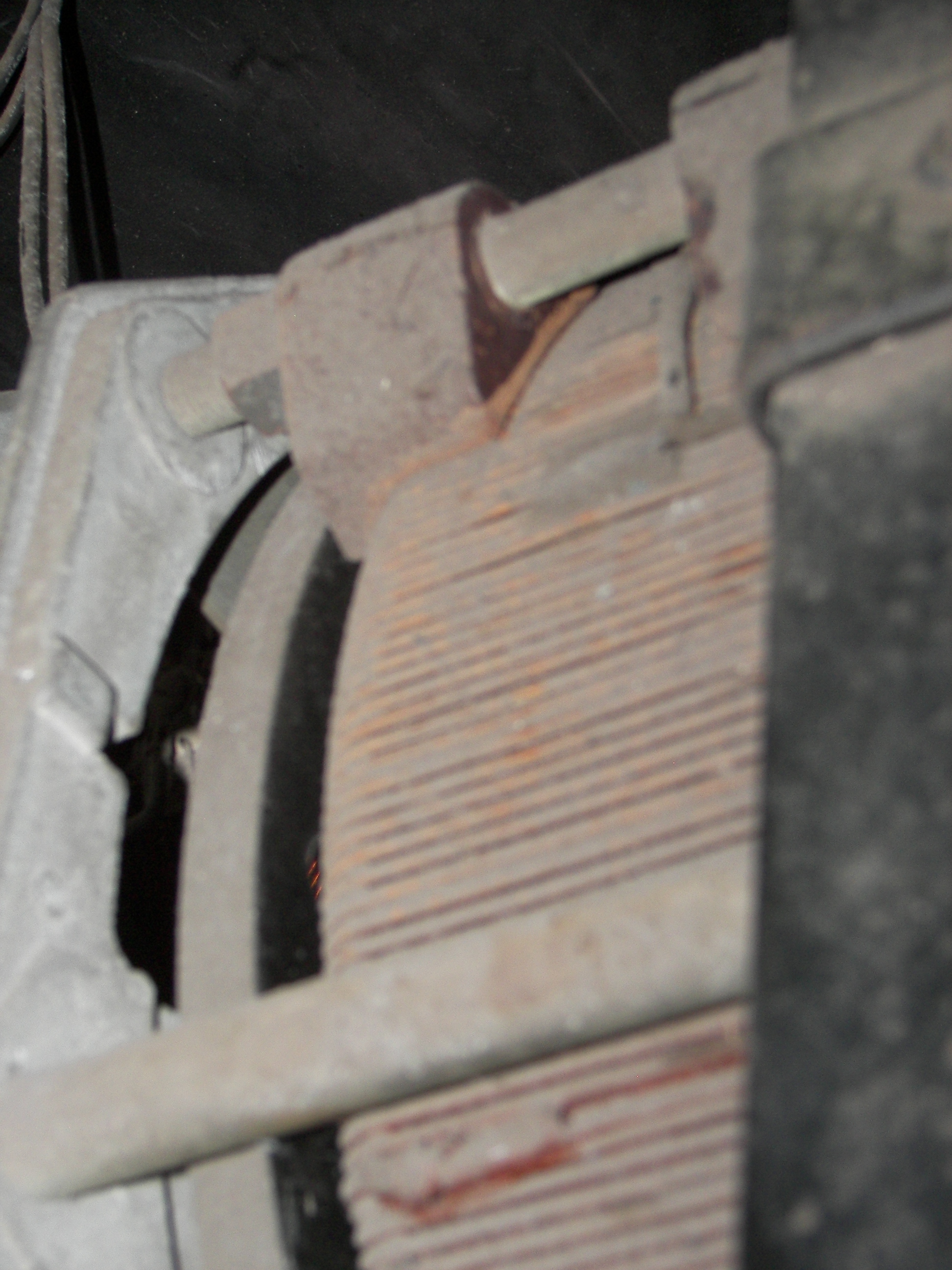
This is the worst of the breakage. It is only the ceramic stand-offs. Coils looked good.

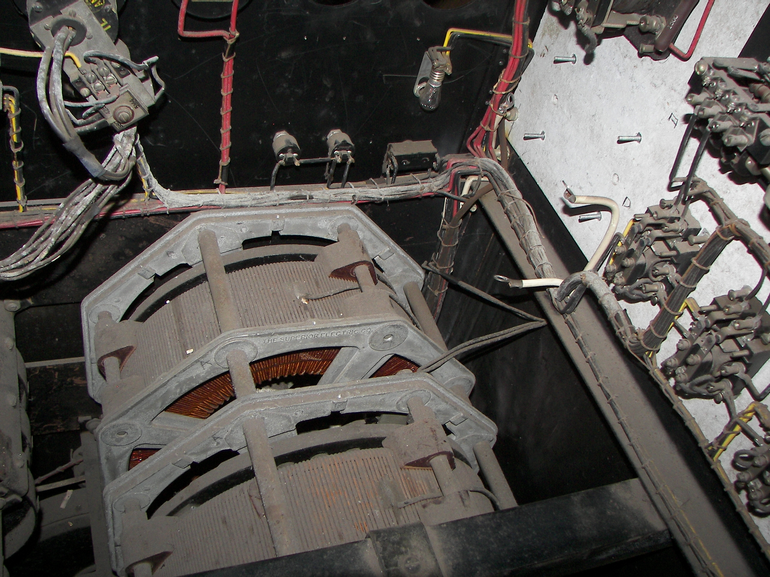
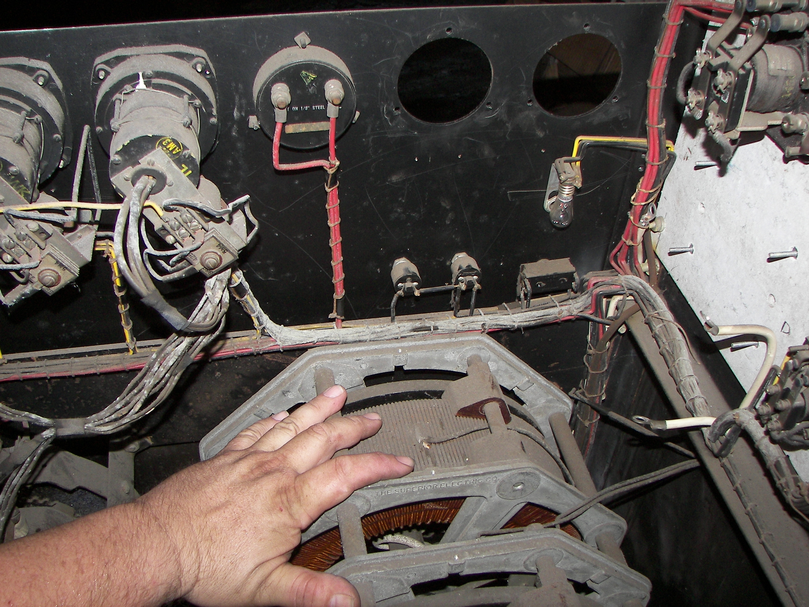
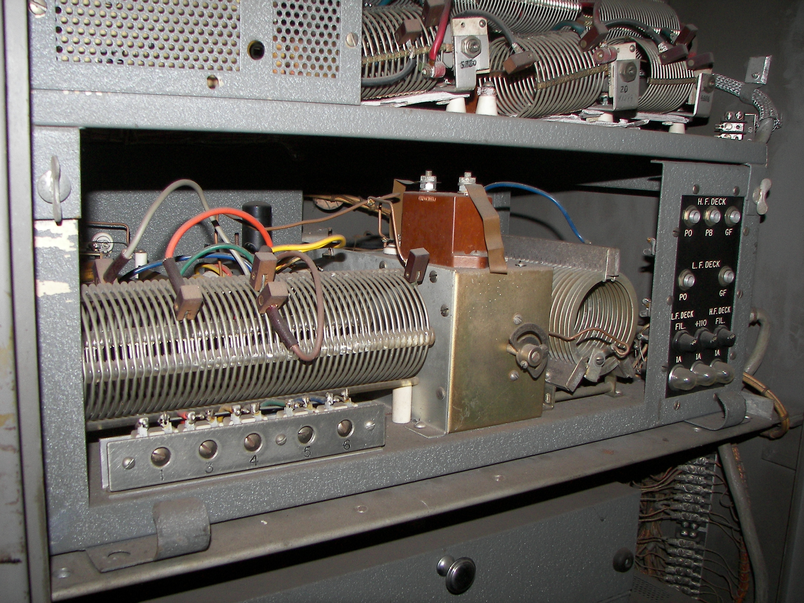
The orange posts are holding the spark gap (protection for the modulation transformer), and barely the envelope of one 807? can be seen. Modulation iron is nice and large.
Substantial but not impossible power supply, three 5R4's, reasonable for 807's and 4D32's.

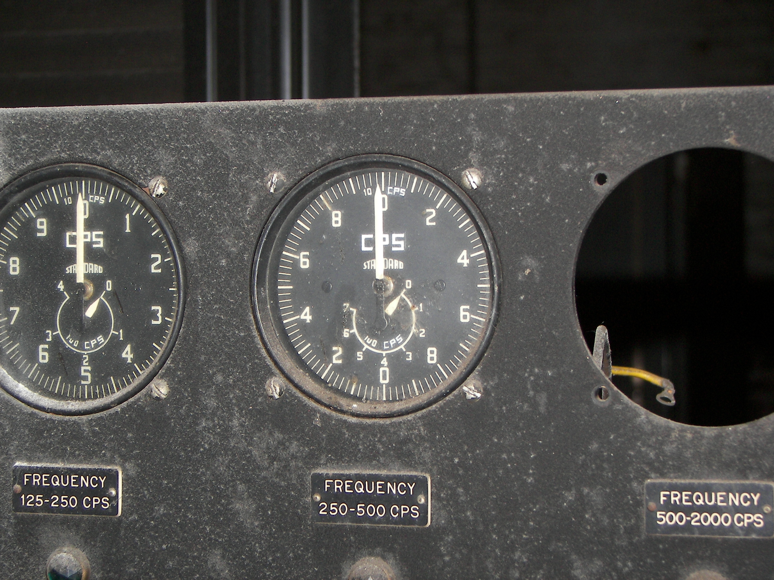
the eight channels units. These apparently drive the RF stages above. To the right may be the power supply for them? In any case, above the channel units, is the operator's panel.
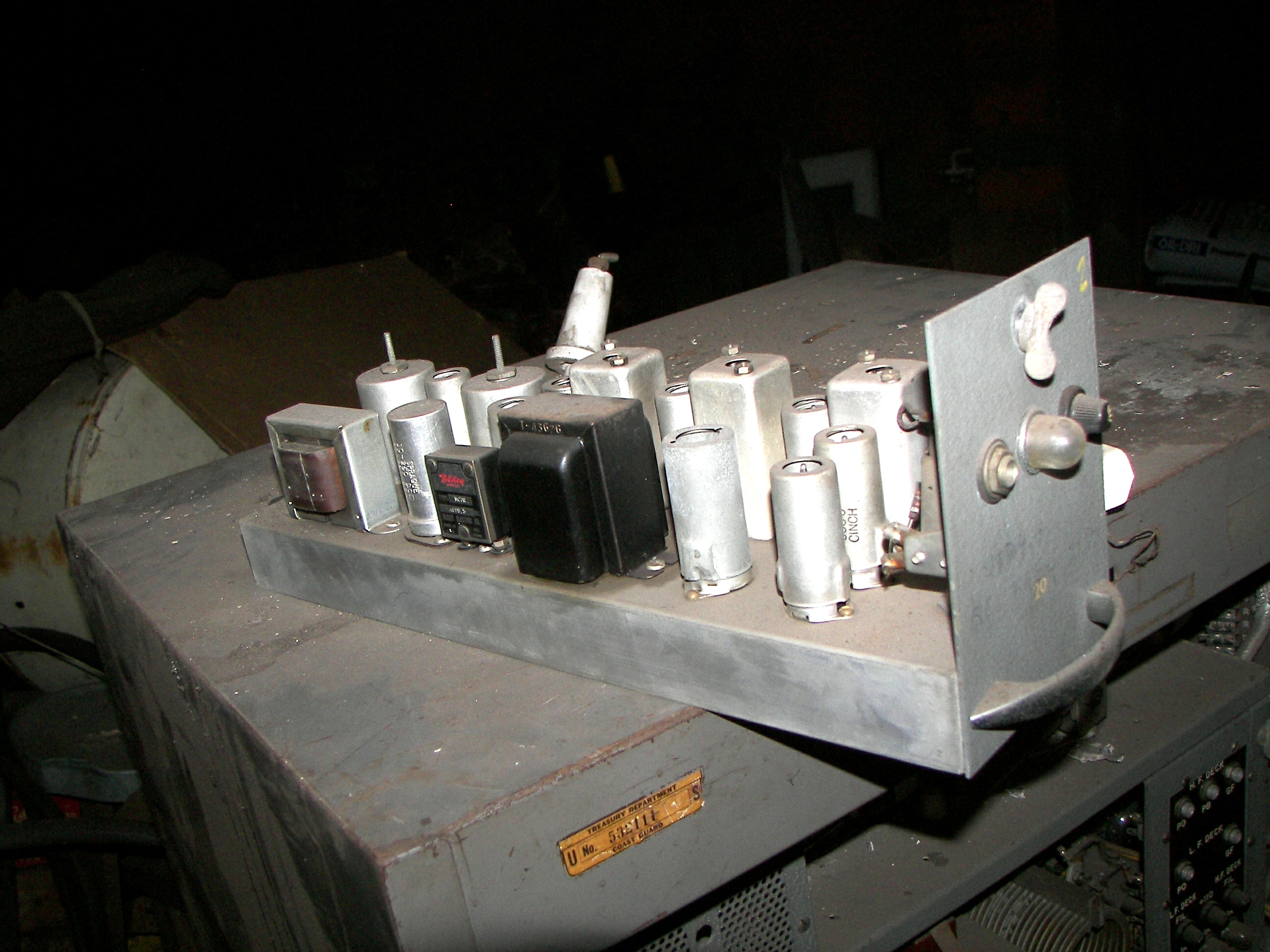
One of the channel units. Note how clean it is. All are like so. It is complex enough at 8 tubes and 5 RF cans that it is probably a complete receiver, but that is speculation.