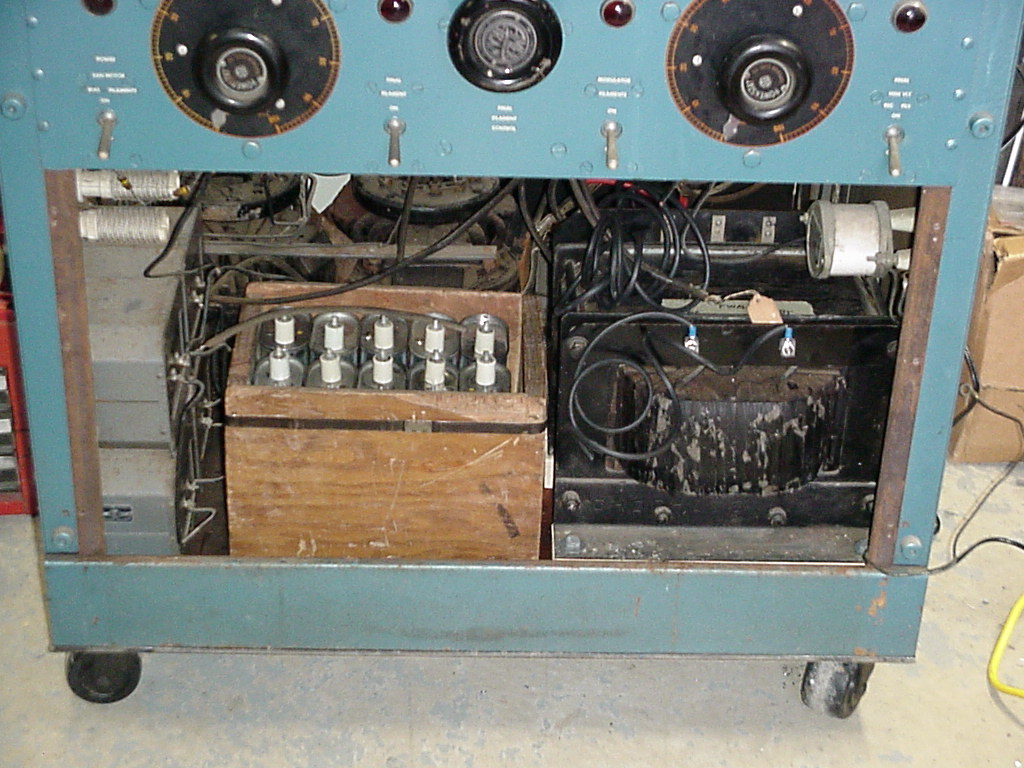
The modulation transformer and capacitor bank have been installed. The oval-shaped 8uF/4KV caps basically just 'sit' in the box, and will be wired together to form two 40uF banks, one for the modulator and one for the PA.
The modulation transformer is given extra HV insulation/protection by mounting it to two 13" long pieces of 2x3 whitewood. The wood rails are mounted to the floor of the cabinet by large bolts which are countersunk so that their heads are 1/2" away from (below) the transformer frame. These bolts can't be seen, as they are underneath the transformer's frame rails. The transformer is then bolted to the wood rails with lag bolts.

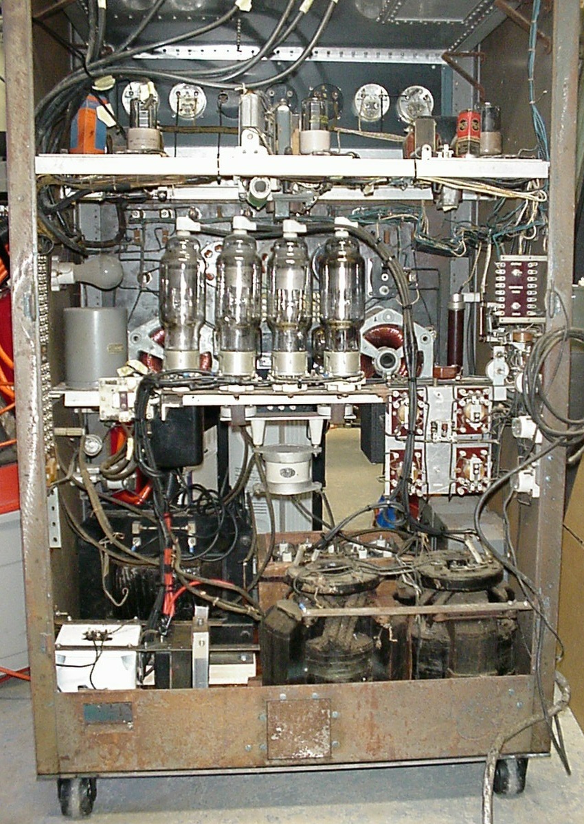
The rear view of the inside of the cabinet. It's getting full. The rectifier filament transformers can be seen mounted in the lower left corner. The large white mica capacitor beneath the rectifier sockets will later be moved to the space above the rectifier filament transformers so that it is closer to the modulation transformer and to make room for the equipment needed for the planned change in modulation circuitry.

The rear view shows the entire state of affairs as of FEB 2004. The unit is 99% ready with only the T/R control relay and the HV power supply's filter section remaining to wire.
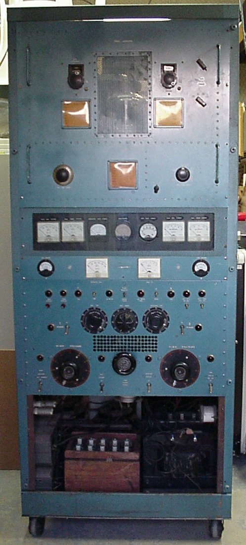
Front view
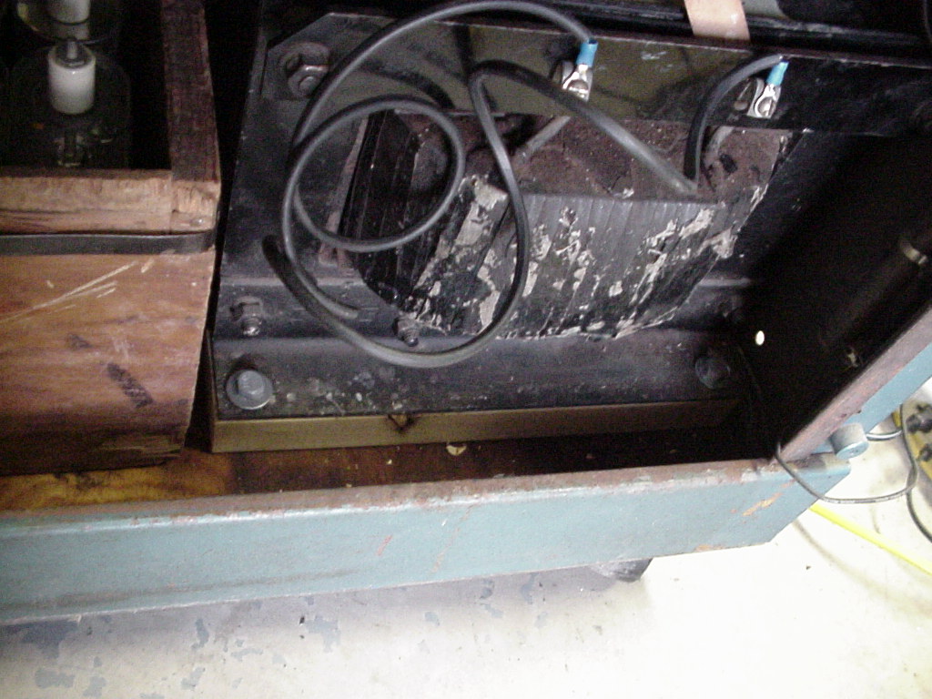
Rear view of the lower section
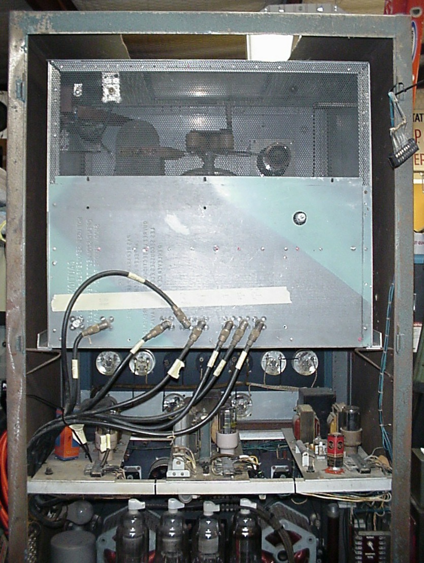
Rear view of the RF deck area. The rear of the RF deck has been enclosed and connections made to the necessary voltages by means of SO-239 connectors as originaly done. The empty SO-239 at the lower left is the RF drive input, and the upper left one is the RF output from the PI-network. The terminal towards the right is the plate voltage (HV) connection for the final amplifier.