00_transmitter_rear.jpg
376 x 1020
|
00_transmitter_rear.jpg 376 x 1020 |
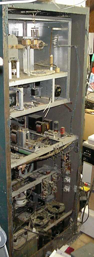
The top section is the RF deck, which sits on two rails and is secured by the front panel. The rear panel of the RF deck is missing. The blue wires to the right are for the 4-1000 filament transformer, blower, airflow switch, and filament voltage monitoring.
Below the RF deck is the low coltage power supply section. To the right is the final bias supply chassis, and in the center is the final screen supply chassis. The modulator bias supply chassis cannot be seen in this view.
The set of rails below the LV supplies is the modulator section. To the right are the modulator filament transformers. The empty space in the center, above the white capacitor, is where the pair of 304TH modulator tubes go.
In the very bottom, the plate transformers can be seen to the right, and some of the 2uF/6KV filter capacitors can be seen on the left.
Page 2 of 26